
Timers and Counters in AT89S52
The 89S52 microcontroller is equipped with three Timers/Counters, which are essential for various timing and counting operations within embedded systems. Each Timer/Counter can be configured to operate in multiple modes, providing flexibility for different applications. The first two Timers/Counters can be utilized for standard timing functions, such as generating precise delays or measuring time intervals, while Timer/Counter 2, with its unique capabilities, can serve specialized counting functions or operate in a different timing mode.
The UART interface is a critical component of the 89S52, enabling asynchronous serial communication. This interface allows the microcontroller to communicate with peripheral devices, including computers and other microcontrollers, over a serial connection. The UART supports various baud rates, ensuring compatibility with different communication standards. This feature is particularly beneficial for applications that require data exchange between multiple devices, such as sensor networks or remote monitoring systems.
The interrupt functionality of the 89S52 enhances the responsiveness of the microcontroller to external events. With the ability to generate interrupts from the internal peripherals as well as external sources, the microcontroller can efficiently handle time-sensitive tasks. The external interrupt sources (INT0 and INT1) are designed to respond to signals from external devices, allowing for real-time processing of inputs from sensors or other digital devices. This capability is crucial for applications such as event-driven systems, where immediate action is required based on external conditions.
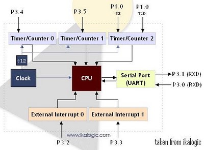
Overall, the combination of versatile Timer/Counters, a robust UART interface, and multiple interrupt sources makes the 89S52 microcontroller a powerful tool for various embedded applications, providing the necessary resources for efficient data processing and communication.Diagram below shows a simplified diagram of the main peripherals present in the 89S52 or 8052 / 8051. There are 3 Timers/Counters in the 89S52. The expression "Timer/Counter" is used because this unit can act as a Counter or as a Timer as per requirement.
Timer/Counter 2 is a special counter that does not behave like the two others, because of some extra functionality. The serial port, using a UART (Universal Asynchronous Receive Transmit) protocol can be used in a wide range of communication applications. With the UART provided in the 89S52 it is easy to communicate with a serial port equipped computer, as well as communicate with another microcontroller.
If all the peripherals described above can generate interrupt signals in the CPU according to some specific events, it can be useful to generate an interrupt signal from an external device that may be a sensor or a Digital to Analog converter. For that purpose there are 2 External Interrupt sources (INT0 and INT1). Posted by Muhammad Ahmed on 16:33. Filed under Counters, How Stuff Works, Microcontroller, Timers. You can follow any responses to this entry through the RSS 2. 0. Feel free to leave a response 🔗 External reference
Related Circuits
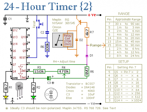
A pair of multi-range timers that provide timing periods of up to 24 hours and beyond. Both timers are fundamentally similar, with the primary distinction being that Version 1 energizes the relay when the time expires, while Version 2...
Telephone ringer utilizing 556 dual timers. This circuit generates ringing tones resembling those of a telephone by employing modulated rectangular waves of varying time periods. The telephone ringer circuit employs two 556 dual timer ICs configured to generate modulated rectangular...
Do not use the on-board relay to switch mains voltage. The board's layout does not provide adequate isolation between the relay contacts and the low-voltage components. If mains voltage switching is required, mount a suitably rated relay in a...

This tutorial explains a real-world application of the 8051 microcontroller. It describes how to interface a 16x2 LCD with the AT89S52 microcontroller. The 16x2 LCD serves as an output device, allowing the controller to display data or information to...
The material is presented as a teaching tool aimed at enhancing understanding and interest in the design of counters. According to R. S. S. Obermann, the design of counters serves as an excellent proving ground for individuals who have...
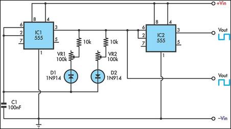
This timer utilizes two 555 integrated circuits (ICs) to adjust the desired output. The variable resistors VR1 and VR2 serve as potentiometers to modify the cycle speed. The circuit can be powered with a 9 to 12-volt power supply,...