
Frequency Meter Circuit
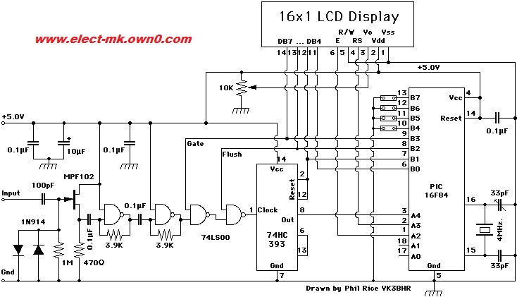
The frequency meter circuit is designed to accurately measure and display frequency across various amateur radio bands, specifically HF (High Frequency), VHF (Very High Frequency), and UHF (Ultra High Frequency). The circuit utilizes a microcontroller or dedicated frequency counter IC to process the incoming signal and convert it into a readable format.
The input stage typically consists of an RF front end, which may include a low-noise amplifier (LNA) to boost weak signals and a bandpass filter to isolate the desired frequency range from unwanted signals. The filtered signal is then fed into the frequency counter, which counts the number of cycles over a defined time period, allowing it to determine the frequency of the incoming signal accurately.
To display the measured frequency, an LCD screen is employed. The microcontroller processes the frequency data and formats it for output to the LCD. The display is designed to show the frequency in a user-friendly manner, often with options for different units (such as MHz or kHz) based on the frequency range being measured.
Power supply considerations are also important in this circuit design. A stable voltage source is required to ensure accurate measurements and reliable operation. It is common to use a regulated power supply or battery to provide the necessary voltage levels for the circuit components.
Additional features may include a calibration function to ensure accuracy, a backlight for the LCD for use in low-light conditions, and possibly a user interface with buttons or a rotary encoder for selecting frequency ranges or modes of operation.
Overall, this frequency meter circuit serves as a valuable tool for amateur radio operators and service technicians, allowing them to monitor and troubleshoot communication equipment effectively across multiple frequency bands.Frequency Meter Circuit of Service Include all the standard frequency bands amateur hf and vhf and uhf And displayed on the LCD screen This is to e. 🔗 External reference
Related Circuits
The following circuit illustrates the AD8531 integrated circuit used for the automatic control of LCD panel backlighting. Features include the ability to compensate for aging effects and other functionalities. The AD8531 is a precision operational amplifier known for its low...
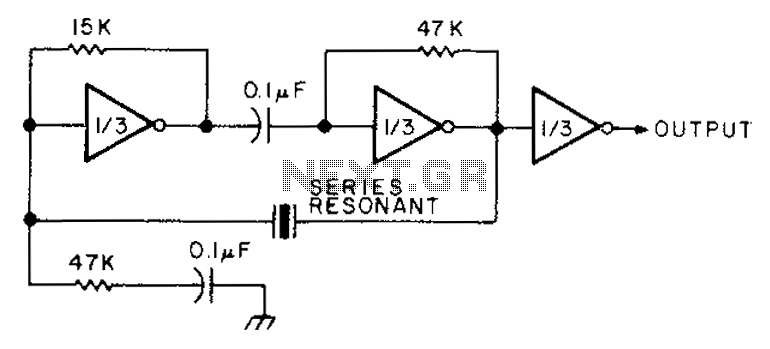
The circuit diagram illustrates the connection of all three components of the series resonant crystal and triple CD4049 inverter. The supply voltage range is between 3 to 15 volts, making it suitable for various applications. This design is compact...
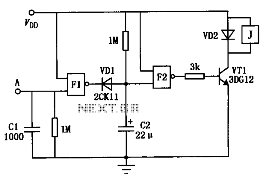
The touch delay switch, as illustrated in the figure, is composed of a CMOS NAND gate and is capable of providing a delay of approximately 10 seconds. It is commonly utilized for the automatic control of lighting in street...
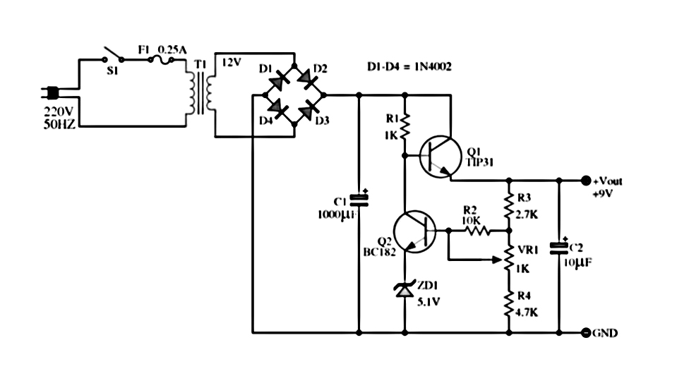
The power supply described utilizes a regulator composed of two NPN transistors. One transistor functions as the power regulator, while the other controls the output voltage. This power supply offers an adjustable output voltage range of 6-12 VDC. The...
This circuit is designed for precise measurement of temperature in degrees Celsius. It features a transmitter section that converts the output voltage from the temperature sensor, which is proportional to the measured temperature, into a frequency signal. This frequency...
This is a small electronic switch that connects a battery to the equipment for a certain amount of time when a push-button is momentarily pressed. The ambient light level has also been considered; when it is dark, the display...
Warning: include(partials/cookie-banner.php): Failed to open stream: Permission denied in /var/www/html/nextgr/view-circuit.php on line 713
Warning: include(): Failed opening 'partials/cookie-banner.php' for inclusion (include_path='.:/usr/share/php') in /var/www/html/nextgr/view-circuit.php on line 713