
ISO102 and OPA27 schematic configuration measuring DC current 500VDV

The circuit operates by utilizing a high-voltage DC source, which is connected to a load (the DC motor) through a sampling resistor. The purpose of the sampling resistor is to create a measurable voltage drop that corresponds to the current flowing through the motor. This voltage drop is proportional to the current, allowing for accurate current measurement.
The OPA27 operational amplifier is used to amplify the voltage signal across the sampling resistor. Its high input impedance and low output impedance make it suitable for this application, ensuring that the measurement does not significantly affect the circuit operation. The amplified signal is then sent to the ISO102 isolation amplifier. The ISO102 is designed to provide electrical isolation between the high-voltage section of the circuit and the low-voltage measuring equipment, which is critical for safety and signal integrity.
The isolation provided by the ISO102 also helps in reducing noise and interference that could be introduced by the motor's operation. Electric motors can generate significant electromagnetic interference (EMI), which can corrupt measurements if not adequately mitigated. By isolating the measurement circuitry from the motor, the circuit can maintain accurate readings even in the presence of such noise.
Furthermore, the circuit includes an offset voltage regulation feature, which allows for fine-tuning of the output signal. This is particularly useful in ensuring that the measurements are accurate and that any inherent offsets in the amplifier circuitry can be compensated for. The gain adjustment potentiometer provides flexibility in scaling the output signal, allowing it to be matched to the requirements of downstream processing or display systems.
Overall, this circuit design effectively combines high-voltage measurement with isolation techniques, ensuring accurate current monitoring while minimizing the impact of noise and interference from high-power components. As shown in FIG constituted by ISO102 OPA27 500VDV DC current measurement circuit. Circuit between + 500V DC voltage source and the sampling resistor in series with a DC motor, the voltage drop across the resistor is detected sampling to detect changes in the motor current, the voltage input to the op amp sample OPA27 amplification, and then later by the IS0102 isolation amplifier output. The characteristics of the circuit is the use of isolation amplifiers, the noise of the big motor circuits with low voltage circuit isolation, avoiding the big noise of electric circuits strong electric circuit interference.
Offset voltage regulation, cf. the gain adjustment potentiometer.
Related Circuits
Approximately 20 years ago, small key-holders that emitted an intermittent beep for a few seconds upon detecting a whistle were quite common. These devices utilized a specialized integrated circuit (IC) that made them unsuitable for home construction. The current...
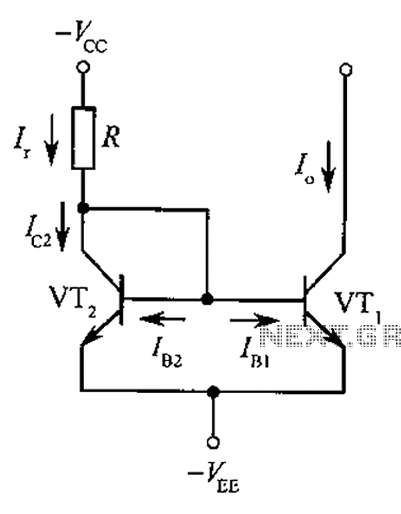
The circuit depicted is a mirror substantially constant current source circuit, in which transistors VT1 and VT2 are matched to each other. The figure illustrates that the current through Ir is equal to Ic2 plus the sum of base...
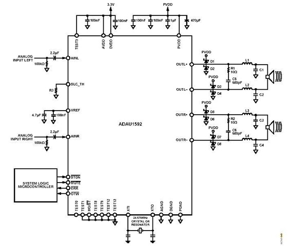
This is a stereo circuit schematic of the ADAU1592, a 2-channel, bridge-tied load (BTL) switching audio power amplifier. The ADAU1592 can be utilized in compact television sets, PC audio systems, and mini-component applications. According to the ADAU1592 datasheet, an...
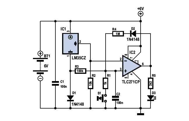
To determine whether it is freezing, one needs to measure the temperature accurately. This requires a reliable temperature sensor. The LM35CZ sensor, which operates within a range of -40 to 110 °C, is suitable for this purpose. It is...
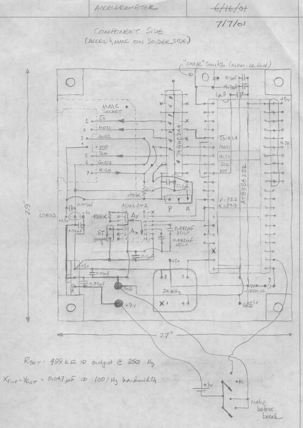
Below is a rough schematic of the layout of the accelerometer PC board looking from the component side. The microcontroller is an Atmel AT89S8252, an 8051 clone. This microcontroller is in-circuit programmable using an SPI interface. The SPI pins...
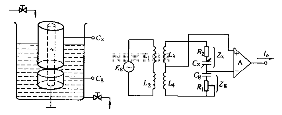
The capacitance change in a capacitive sensor is directly converted into electrical parameters, which are then unified for signal transmission, processing, and display. These electrical parameters can be categorized into resistive, capacitive, and inductive types. This explanation focuses on...