
FSK Demodulator

The FSK (Frequency Shift Keying) demodulator is a crucial component in digital communication systems, particularly for applications involving the transmission of digital serial data. The primary function of the FSK demodulator is to convert the frequency-modulated signals back into their original digital form, allowing for the accurate retrieval of transmitted information.
An FSK demodulator typically operates by detecting the frequency shifts in the incoming signal. It identifies two distinct frequencies that represent binary data: one frequency for a binary '1' and another for a binary '0'. The demodulation process involves filtering the received signal to eliminate noise, followed by the detection of the frequency changes.
The circuit may include components such as a bandpass filter to isolate the frequencies of interest, a phase-locked loop (PLL) for frequency detection, and a comparator to convert the detected frequencies into a digital output. The output is usually a serial stream of bits that can be processed by a microcontroller or other digital logic devices.
In terms of implementation, the FSK demodulator can be designed using discrete components or integrated circuits (ICs) specifically tailored for demodulation tasks. The choice of components will depend on factors such as the required data rate, signal quality, and the specific application environment.
Overall, the FSK demodulator is essential for ensuring reliable communication in systems that utilize FSK modulation, enabling the seamless transition from analog signals back to their original digital format for further processing and analysis.This FSK demodulator convert the FSK signal to serial digital signal. FSK modulation is used to transmit digital serial data, and we need to demodulate it to. 🔗 External reference
Related Circuits

Frequency shift keying (FSK) is a widely used digital modulation technique for data transmission. Common applications of FSK modulation encompass both wired and wireless data transmission, as well as infrared remote controls for consumer electronic devices. FSK demodulation can...
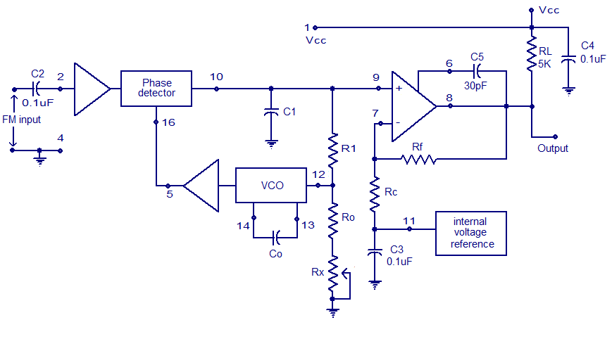
A simple PLL FM demodulator circuit using the IC XR2212 is presented. The XR2212 is a highly stable, monolithic PLL (phase-locked loop) IC specifically designed for communication and control system applications. It operates within a frequency range of 0.01...
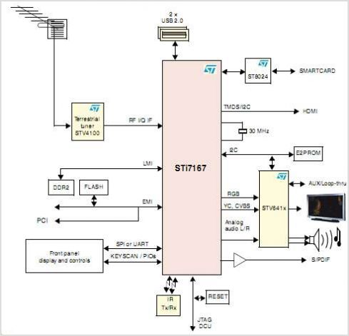
The STK672-050 is a unipolar constant-current chopper-type externally-excited 4-phase stepping motor driver hybrid integrated circuit (IC) that utilizes MOSFET power devices. It features a built-in microstep operation-supported 4-phase distributed controller, enabling the realization of a high torque, low vibration,...
Figure 7-2 illustrates the FSK (Frequency Shift Keying) signal demodulation circuit, which is built using a digital phase-locked loop. This circuit features two oscillators operating at distinct frequencies: crystal oscillator X with a frequency of 983.04 kHz and crystal...
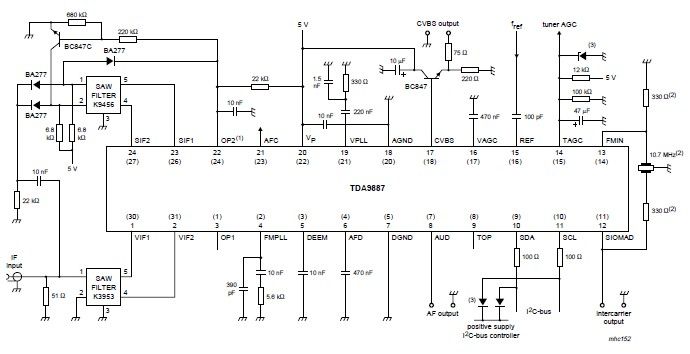
The integrated circuit (IC) is a multistandard vision and sound intermediate frequency (IF) phase-locked loop (PLL) demodulator that operates without the need for alignment. It supports multiple standards, including PAL, SECAM, and NTSC, and is capable of processing both...
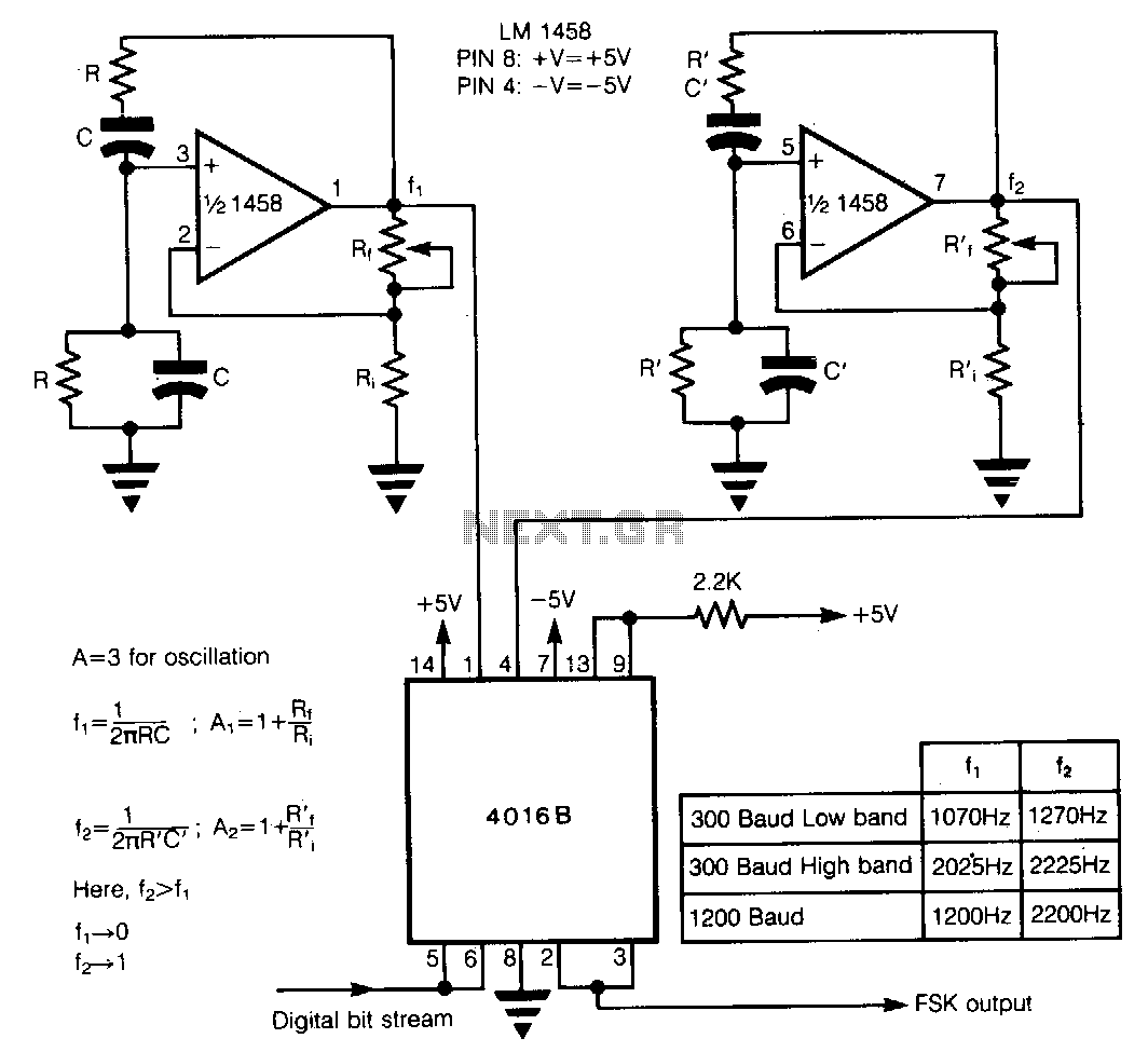
In Frequency Shift Keying (FSK), two distinct frequencies are utilized to represent the binary digits 0 and 1. The core of the circuit comprises two Wien-bridge oscillators constructed with a dual operational amplifier LM1458, each generating one of the...