
FSK Demodulator Using LM565

The FSK (Frequency Shift Keying) demodulator serves a critical function in digital communication systems by translating frequency-modulated signals back into their original digital form. It operates by detecting the frequency variations of the incoming signal, which correspond to binary data. The demodulator typically includes several key components such as bandpass filters, phase-locked loops (PLLs), and comparators.
In a typical application, the incoming FSK signal is first passed through a bandpass filter, which isolates the frequency components of interest while attenuating unwanted noise and interference. The filtered signal is then processed by a phase-locked loop, which tracks the frequency shifts and maintains synchronization with the incoming data stream. The PLL generates a reference signal that is phase-aligned with the incoming FSK signal, allowing for accurate detection of the frequency changes.
After synchronization is achieved, the output of the PLL is fed into a comparator circuit. The comparator compares the phase of the reference signal with the incoming signal, generating a binary output that represents the original digital data. This output can then be further processed or transmitted as needed.
FSK demodulators can be implemented in both analog and digital forms, with digital implementations often providing greater accuracy and flexibility. They are widely used in various applications, including wireless communication systems, data modems, and telemetry systems, where reliable transmission of digital data over radio frequencies is essential.The FSK demodulator is the electronics device that converts the FSK signal to serial digital signal. To transmit digital serial data we use FSK modulation and.. 🔗 External reference
Related Circuits

A simple and efficient PWM lamp dimmer utilizing the timer IC NE555 is presented in this article. Traditional linear regulator-based dimmers achieve a maximum efficiency of only 50%, which is significantly lower than PWM-based dimmers that can exceed 90%...

A simple frequency meter or frequency counter circuit featuring an LCD display and an AVR microcontroller. This includes a DIY schematic circuit diagram and embedded C code. The frequency meter circuit is designed to measure the frequency of input signals...

This light sensor circuit, utilizing a photosensor, serves as a bridge between light and electronics. It is constructed using an operational amplifier and the PIC16C63 microcontroller to control the sensor. While the circuit is not intended for precision applications,...
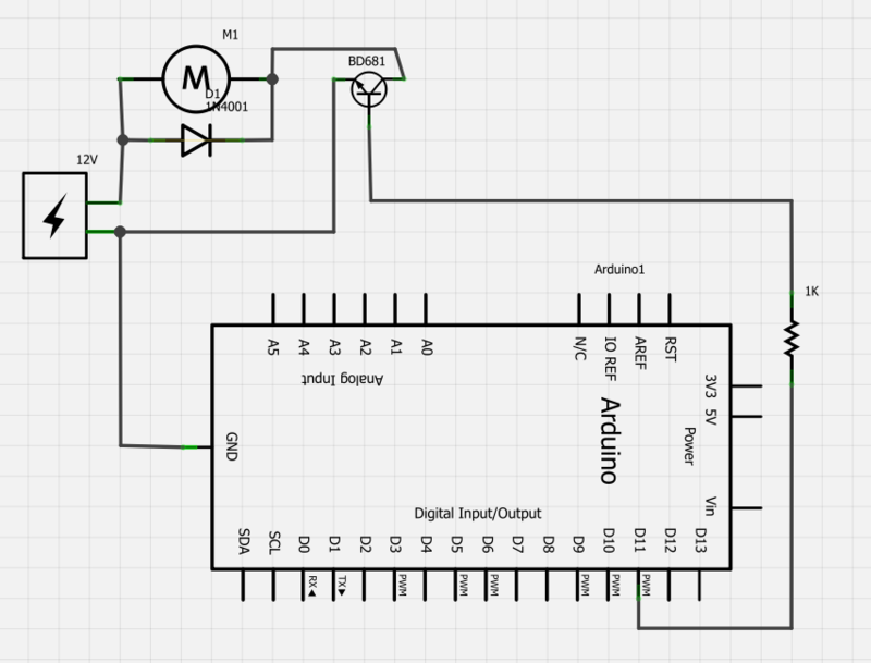
Power a 12V fan using a Darlington transistor to control the speed from an Arduino. When wired as described, nothing happens even though a PWM signal is being sent. It is suggested to edit the question and ensure the...
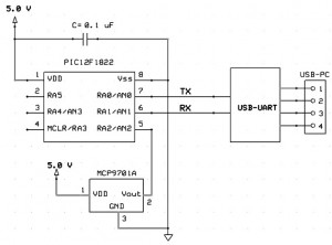
This project outlines a simple and cost-effective method for integrating a digital thermometer and data logging capability into a PC. It utilizes a PIC microcontroller to obtain temperature data from the Microchip MCP9701 sensor and transmits this information to...

The project was inspired by attending the HamRadio 2000 Millennium Ham Meet in Hyderabad on December 22, 23, and 24, where interactions with esteemed individuals such as VU2NR and VU2RM took place. The latest design by VU2NR, the NR-80,...