
transistors Having difficulties using a darlington (BD681) to drive a 12V fan from an Arduino
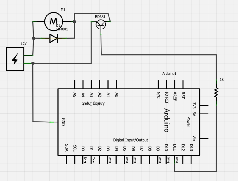
To power a 12V fan using a Darlington transistor for speed control via an Arduino, the following circuit configuration is advised. The Darlington transistor, which consists of two bipolar junction transistors (BJTs) connected together, provides high current gain and is suitable for switching applications.
The circuit should include an NPN Darlington transistor, such as the TIP120, which is capable of handling the required current for the fan. The Arduino will output a PWM signal to control the fan speed. Connect one of the PWM-capable digital pins of the Arduino (for example, pin 9) to the base of the Darlington transistor through a current-limiting resistor (typically 1kΩ). This resistor is essential to protect the Arduino from excess current.
The collector of the Darlington transistor should be connected to the positive terminal of the 12V power supply, while the emitter connects to one terminal of the fan. The other terminal of the fan should be connected to the ground of the power supply. It is crucial to ensure that the ground of the Arduino is also connected to the ground of the 12V power supply to establish a common reference point.
For additional protection, a flyback diode (e.g., 1N4001) should be placed in parallel with the fan terminals to prevent back EMF generated by the inductive load when the fan is switched off. The cathode of the diode connects to the positive terminal of the fan, while the anode connects to the ground side.
In summary, the circuit consists of an Arduino sending a PWM signal to a resistor connected to the base of a Darlington transistor, which in turn controls the fan powered by a 12V supply. Proper connections and component selection are critical to ensure functionality and prevent damage to the components.Power a 12v fan using a darlington so I can control the speed from an Arduino. When I wire up as below nothing happens, even though I`m sending a PWM signal: Please draw a proper circuit. Edit your question and hit Ctrl+M, the current image is unreadable. Check your breadboard, most rows along the side are have one or two interruptio ns half way (Arduino`s GND connection). Possibly add a picture of your setup aswell. jippie Apr 13 `13 at 20:16 🔗 External reference
Related Circuits
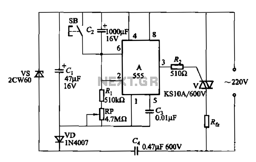
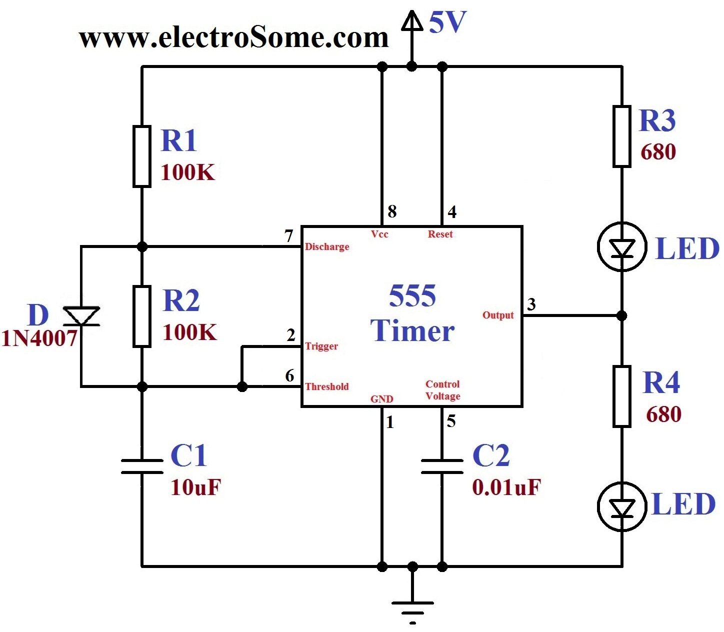
The circuit utilizes a 555 Integrated Circuit (IC) configured as a delay circuit. It transitions from a low to a high state after a button (SB) is pressed, initiating a delay before the output terminal goes high. The output...

FAN7710 Ballast Control circuit design for Compact Fluorescent Lamps electronic project. The FAN7710 is a specialized integrated circuit designed for the control of ballast systems in compact fluorescent lamps (CFLs). This circuit typically operates in a high-frequency range, facilitating efficient...

The circuit is designed to regulate a dual power supply that provides +12V and -12V from the AC mains. Such a power supply is an essential tool for an electronic hobbyist's workbench. The schematic of the circuit includes components...
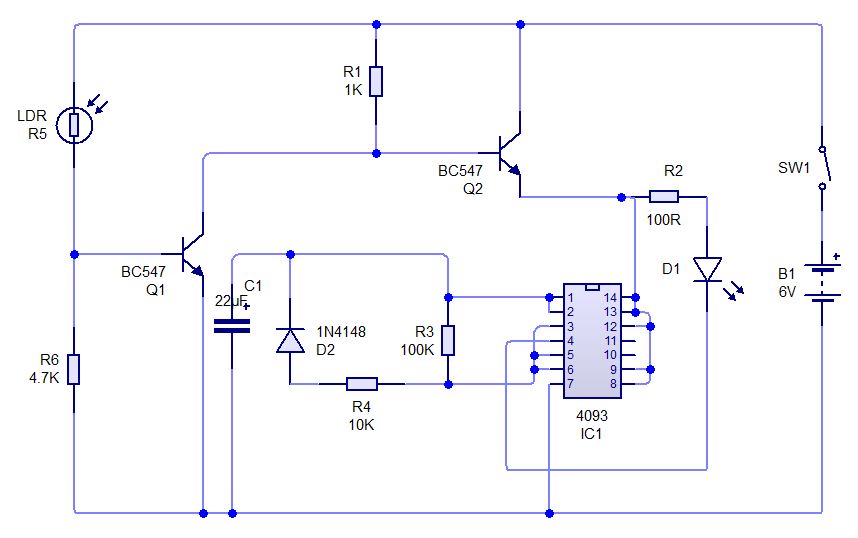
This is a simple experiment involving a Light Dependent Resistor (LDR) and a CD4093 integrated circuit. It modifies a previous dark sensor project that utilized two transistors. In this configuration, when light falling on the LDR is obstructed, the...
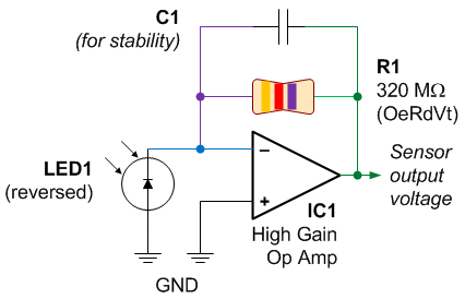
One of the first lessons that electronics students learn is that an LED emits light when current flows through it. However, it is also true that when an LED is connected in reverse, it can generate a current flow...
A dancing light can be easily constructed using a 555 timer wired in astable mode. This circuit alternately blinks two LEDs with a certain delay and can be modified to include additional LEDs or to control incandescent lamps. The...