
Fun with Arduino

The Arduino board features built-in power regulation circuitry that delivers a stable 5 volts to the ATMEGA328P. However, since the Arduino will no longer be used, a custom power supply circuit must be created. Additionally, a clock source for the microcontroller is necessary, which is achieved using a 16 MHz crystal oscillator and 22 pF capacitors.
The circuit operates as follows: a 9-volt power supply from an adapter is connected to a 1N4001 diode. This diode allows current to flow in one direction only, providing protection if the adapter is connected incorrectly. The voltage is then reduced to 5 volts by a 7805 voltage regulator, which maintains a steady output. Capacitors of 10 µF and 100 µF are used to smooth any voltage ripples in the 5-volt supply. This regulated power is supplied to the ATMEGA328P microcontroller. The 16 MHz crystal oscillator, along with the 22 pF capacitors, generates a consistent clock signal for the microcontroller. Furthermore, a 10 kΩ resistor is employed to keep the reset pin of the microcontroller high, ensuring that the chip executes its program.
When selecting a DC power adapter for this circuit, it can accommodate various adapters, with 9 volts being a recommended choice. While it is possible to use a slightly higher voltage, any excess will be dissipated as heat by the 7805 regulator, potentially necessitating the addition of a heat sink if the voltage is too high. Conversely, using a voltage lower than 9 volts may lead to insufficient output from the regulator. The current rating of the adapter should also be considered; a 500 mA rating is suitable as it matches the USB port rating typically used to power the Arduino. For larger projects, a 1 amp adapter may be advisable. Finally, the polarity of the adapter must be checked, as most adapters indicate the polarity of the tip and sleeve on the label. Proper wiring of the jack according to this specification is essential for correct operation.The term Arduino actually refers to a system of components that include the board, the microcontroller, the boot-loader, and the programming environment. It is a system designed to `protect` the user from a lot of the complication that is part of microcontroller programming.
At the heart of the Arduino board is a microcontroller called the ATMEGA3 28P. The Arduino board acts like a space suit for the ATMEGA, providing life support and doing its best to protect the chip from damage. At the end of the day, the Arduino is a development board. While you can make the Ardino a permanent part of you project, once you have finished with the development phase of your design, it is often cleaner and less expensive to replace it with a stand alone ATMEGA microcontroller circuit.
This is what we are going to build. The Arduino board has built in power regulation circuitry that provides a steady 5 Volts to the ATMEGA328P. But, since the Arduino is going bye-bye, we have to build our own power supply circuit. We also need to provide a clock source for the microcontroller. The 16Mhz crystal and 22pF capacitors take care of that. Let`s look at what this circuit is doing. The 9 volt power from your adapter is being fed to a 1N4001 diode. This diode will only allow current to pass in one direction so if the adapter is connected backwards, the circuit will be protected.
The 7805 regulator then drops the voltage down to 5 volts and holds it there. The 10uF and 100uF smooth out any ripples in the 5 volt supply. This steady 5 volt power is supplied to the ATMEGA328P chip. The 16Mhz crystal and 22pf capacitors supply a steady clock signal to the microcontroller. Finally, in 10K resistor holds the microcontrollers `reset` pin high, so the chip will run it`s program. It`s a very simple circuit. A couple of notes about choosing a DC Power adapter. This circuit will accept a variety of power adapters, but 9 volts is a good choice. You could go a little higher but the extra voltage will just be wasted as heat from the 7805 regulator.
You may need to add a Heat-Sink if you go too high. If you go lower than 9v you may find the regulator may have difficulty putting out it`s full 5 volts. Also check the current rating of the adapter. I am using a 500mA unit. This is a fair choice as it is the same rating as the USB port that was probably powering your Arduino not long ago.
If your project is larger, you may want to go with a 1 amp unit. Finnaly, check the polarity of your adapter. Most adapters have a symbol printed on the label that shows the polarity of the tip and sleeve of it`s power plug. You can see the symbol in the photo below. This one is showing that the sleeve of the plug is positive. You can use either type, just make sure you wire up your jack accordingly. 🔗 External reference
Related Circuits
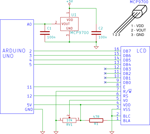
A temperature sensor (MCP9700 linear active thermistor IC) and LCD are connected to the Arduino in this tutorial. The Arduino reads the temperature from the MCP9700 on analog pin A0 and displays the temperature on the LCD. The circuit involves...
Significant overengineering was necessary to replicate a previous capacitive scanner. At the local hackerspace OSAA, a brainstorming session was initiated with Pedersen, AsbjG rn, and Flemming, who quickly generated numerous creative ideas. The discussion took an interesting turn when...
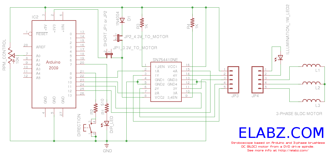
Constructing a stroboscope (zoetrope) using an Arduino and the spindle motor from a damaged Xbox 360 DVD drive. Includes zoetrope animations, Arduino code, and circuit schematic. The project involves utilizing an Arduino microcontroller to control the spindle motor extracted from...
This article discusses the creation of a digital thermometer using the Arduino Uno. The temperature sensor employed is the LM35DZ, although it can be substituted with other sensors like the DS18B20. The sensor detects temperature and sends the data...
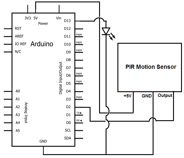
Once the motion sensor detects motion, the Arduino can be programmed to activate an LED, turn on a motor, sound a buzzer, etc. In this circuit, for simplicity, an LED will be turned on when the motion sensor detects...
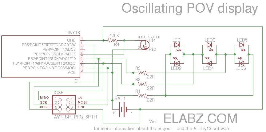
Smart Valentine's Day gift - a movement-sensing box of chocolates with an LED message. Circuit diagram and instructions for building the project using ATtiny13 and Arduino. The project involves creating a movement-sensing box of chocolates that incorporates an LED display...
Warning: include(partials/cookie-banner.php): Failed to open stream: Permission denied in /var/www/html/nextgr/view-circuit.php on line 713
Warning: include(): Failed opening 'partials/cookie-banner.php' for inclusion (include_path='.:/usr/share/php') in /var/www/html/nextgr/view-circuit.php on line 713