
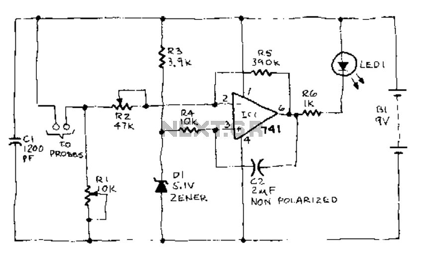
Mains Frequency Monitor
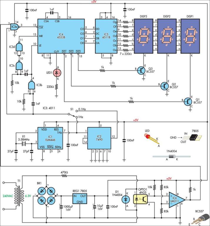
The frequency counter circuit operates by measuring the frequency of an alternating current (AC) signal, specifically designed for 240VAC mains supply applications. The circuit can accurately measure frequencies from 0 to 999Hz, making it versatile for various applications, including monitoring industrial equipment that operates at 400Hz.
The primary components of the frequency counter include a microcontroller or frequency measurement IC, which processes the input signal and converts it into a readable frequency output. A transformer may be used to step down the high voltage AC mains supply to a safer level suitable for the circuit. Additionally, rectification and filtering components are necessary to convert the AC signal to a DC signal, which the microcontroller can process.
The circuit may also feature a display module, such as a seven-segment display or an LCD, to provide real-time frequency readings. Input protection components, including fuses and voltage dividers, are crucial to safeguard the circuit from voltage spikes or surges typically present in AC mains.
For accurate readings, the circuit should be calibrated to account for any phase shifts or signal distortions that may occur due to the characteristics of the AC supply. Proper grounding and shielding techniques should be employed to minimize electromagnetic interference, ensuring the frequency counter operates reliably in various environments.
Overall, the design and implementation of this frequency counter provide a practical solution for monitoring AC frequencies, which can be invaluable in maintenance and diagnostics for electrical systems.Here is a simple frequency counter designed to monitor the 240VAC mains supply. It as a frequency range of 0-999Hz, so it could also be used with 400Hz eq.. 🔗 External reference
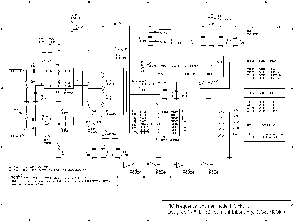
Related Circuits
This is an image Schematic. No Description available. The provided input indicates that there is an image schematic without any accompanying descriptive details. In the absence of specific schematics or circuit details, it is essential to consider the typical...
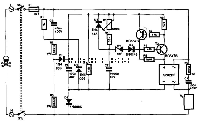
This timer can be integrated into a power line to provide a controllable delay before a load is activated. The mains voltage is reduced by capacitor C3 and rectified to yield approximately 30 V across capacitor C1. This voltage...
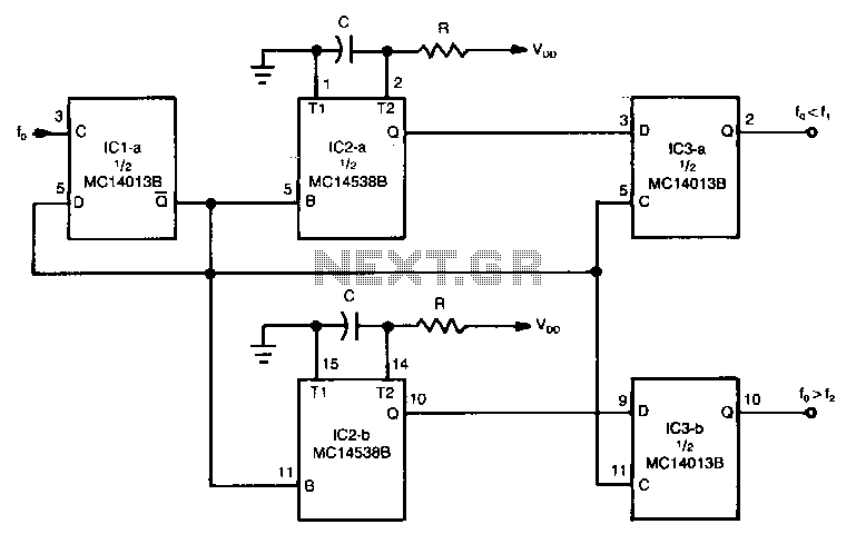
The circuit can be used to determine whether an input signal falls within a specific frequency range. The device comprises three integrated circuits (ICs), including a dual monostable multivibrator and two dual D-type flip-flops. The signal whose frequency is...
When the soil is moist, the LED glows. If the moisture falls below a certain predetermined level, the LED begins to flash. If there is still less moisture, the LED turns off. To calibrate, connect the battery and insert...
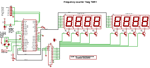
C code for a frequency counter circuit operating up to approximately 50 MHz, utilizing a multiplexed seven-segment display and employing Timer 1 to count the edges of the input signal. The frequency counter circuit described operates effectively within the range...
Depending on the external circuit connection, the 555 timer can be configured for various modes such as start delay, trigger delay, multi-harmonic oscillation, and other operational conditions. It functions as a versatile tester with the inclusion of some RC...
Warning: include(partials/cookie-banner.php): Failed to open stream: Permission denied in /var/www/html/nextgr/view-circuit.php on line 713
Warning: include(): Failed opening 'partials/cookie-banner.php' for inclusion (include_path='.:/usr/share/php') in /var/www/html/nextgr/view-circuit.php on line 713