
Rain alarm
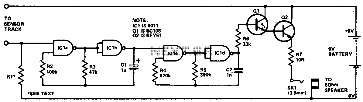
The circuit design consists of two primary oscillators, each employing NAND gates to create square wave outputs. The first oscillator, comprising IC1a and IC1b, operates by utilizing one gate as an inverter while the other gate serves as a control mechanism. The control input of the second gate is critical for determining the operational state of the oscillator. When the control input is low, the oscillator is disabled, preventing any oscillation from occurring.
The sensitivity control is implemented through a high-value resistor (R1), which connects the control input to ground. This configuration ensures that the oscillator remains inactive until a certain threshold is met, specifically when moisture is detected on the sensor track. The presence of moisture effectively pulls the control input high, allowing the oscillator to generate a square wave output with a frequency of approximately 10 Hz.
This 10 Hz square wave output is then used to gate the second oscillator, which consists of IC1c and IC1d. This second oscillator operates at a higher frequency of 500 Hz, providing a rapid pulsing signal that is suitable for driving a loudspeaker. The output from the 500 Hz oscillator is routed through resistor R6, which serves to limit the current to the loudspeaker and protect the circuit from potential damage.
To amplify the signal for the loudspeaker, a Darlington pair configuration is employed using transistors Q1 and Q2. This arrangement provides high current gain, allowing the circuit to drive the loudspeaker effectively. Resistor R7 is included in the circuit to further ensure the stability and proper operation of the transistors within the Darlington pair. Overall, this circuit effectively combines sensor input with oscillator functionality to produce an audible signal, demonstrating a practical application of digital logic in electronic design.The circuit uses four NAND gates of a 4011 package. In each oscillator, while one gate is configured as a straightforward inverter, the other has one input that can act as a control input. Oscillator action is inhibited if this input is held low. The first oscillator (ICla and IClb) has this input tied low via a high value resistor (Rl) that acts as a sensitivity control.
Thus this oscillator will be disableduntil the control input is taken high. Any moisture bridging the sensor track will so enable the output which is a square wave at about 10 Hz This in turn will gate on and off the 500 Hz oscillator formed by IClc and ICld. This latter oscillator drives the loudspeaker via R6, the Darlington pair formed by Q1 and Q2, and resistor R7. 🔗 External reference
Related Circuits
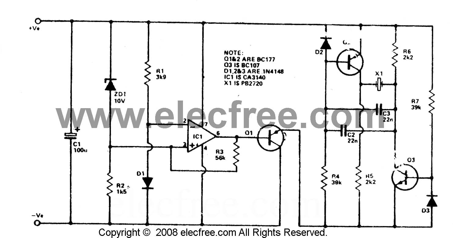
To check the battery in a car, an easy circuit utilizing the IC CA3140 and a transistor is employed. The voltage level of an automobile battery is influenced by many factors, and if it is high... The circuit for checking...

This is a simple single-zone burglar alarm circuit. Its features include automatic exit and entry delays. It is designed to be used with commonly available normally-closed input devices such as magnetic reed contacts, micro switches, foil tape, and passive...
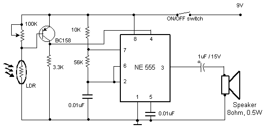
This circuit triggers an alarm when its LDR (Light Dependent Resistor) sensor is exposed to light from the sun or a lamp. A 555 astable multivibrator is utilized to generate a tone of approximately 1 kHz upon detecting light....
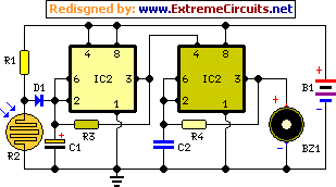
The main purpose of this design is to address a minor flaw in the widely used Fridge Door Alarm circuit, which has been available on this website since 1999 and has been constructed by many hobbyists. This circuit ceases...
This circuit project automatically activates a night lamp when the bedroom light is turned off. The lamp stays illuminated until the light sensor detects daylight. The circuit operates using a light-dependent resistor (LDR) as the primary sensor to detect ambient...
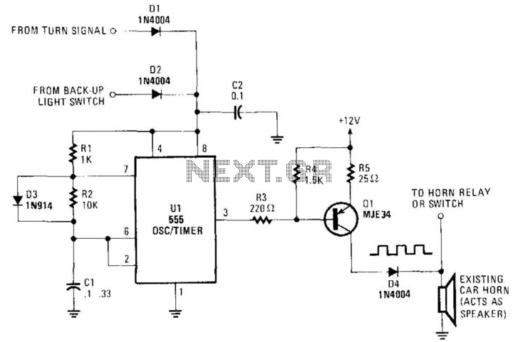
An auto horn operates as a speaker within a limited audio-frequency range. This circuit utilizes a 555 timer configured as an oscillator to drive an MJE34 transistor, which subsequently activates the horn. Normal horn operation is maintained through the...
Warning: include(partials/cookie-banner.php): Failed to open stream: Permission denied in /var/www/html/nextgr/view-circuit.php on line 713
Warning: include(): Failed opening 'partials/cookie-banner.php' for inclusion (include_path='.:/usr/share/php') in /var/www/html/nextgr/view-circuit.php on line 713