
G3XTZ DF Rx Details
The receiver design incorporates a range of components and configurations to ensure effective signal processing and direction finding. The printed circuit board layout is crucial, as it must accommodate the various components while minimizing interference and maintaining signal integrity. The use of a tuned ferrite rod aerial enhances the receiver's sensitivity to directional signals, while the inclusion of multiple amplification stages ensures that the received signals are sufficiently boosted before processing.
The TCA440 integrated circuit plays a central role in the receiver's functionality, integrating multiple stages of signal processing into a compact form factor. The balanced mixer and local oscillator work in tandem to convert incoming radio frequencies into an intermediate frequency, allowing for easier filtering and amplification. The mechanical filter's bandwidth is specifically chosen to optimize signal clarity, which is essential for accurate direction finding.
The design also considers user interface aspects, such as the volume control and tuning mechanisms, ensuring that operators can efficiently adjust settings for optimal performance. The choice of components, such as varicap diodes for tuning, reflects a balance between performance and cost-effectiveness, making the receiver accessible for various applications.
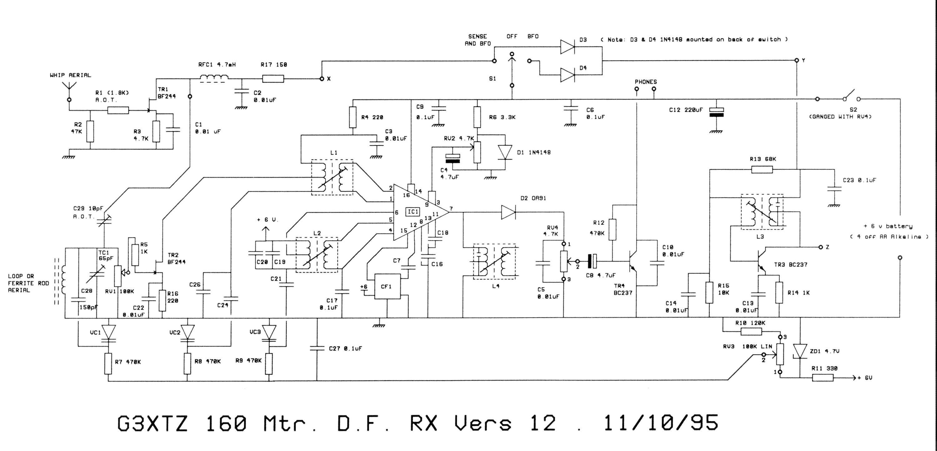
Overall, this receiver design exemplifies a thoughtful approach to electronic circuit design, integrating various technologies to achieve a compact, efficient, and effective direction-finding solution.The receiver is built on a single-sided printed circuit board which measures 2 by 4. 3 inches. The small size means that the board can be fitted into a wide variety of enclosures, which should be well screened. The main directional signal is picked up by a tuned ferrite rod (or loop) aerial and fed, via the R. F. attenuator (RV1) to a low-noise FET R. F. amplifier (TR2). A second FET R. F. stage (TR1) amplifies the signal from a vertical whip aerial and can be switched into circuit to give a heart-shape response so that the direction of received signal can be determined. This direction is not accurate, but serves to eliminate one of the two sharp null directions that the ferrite aerial provides.
The amplified signal is tuned in a Hi-Q coil (L1) and fed into the TCA440 receiver integrated circuit. This I/C includes R. F. amplifier, balanced mixer, separate local oscillator, I. F. amplifier and voltage stabilizer. The local oscillator is tuned by L2 with VC3 and covers 2. 265 to 2. 455 MHz which converts the incoming signals of 1. 81 to 2. 00 MHz to a 455 kHz I. F. This signal is fed from the mixer through the 5. 5 kHz bandwidth Mechanical filter (CF1) and back into the TCA440 I. F. amp. The amplified signal is rectified by diode D2 and appears as audio across the volume control (RV4). Automatic gain control is not normally used in a direction finding receiver (this would mask the effect of rotating the aerial) so the gain of the R.
F. and I. F. amplifiers are set by a fixed, stabilized voltage ( about 0. 7 Volt maximum ) from trimmer resistor RV2. Adjustable audio levels are fed from the volume control to a single, high gain audio amplifier which drives the headphones to adequate level. Medium to high impedance headphones are preferred. TR4 with L3 form a simple Beat Frequency Oscillator which can be switched in to enable reception of C.
W. or SSB signals. When a bearing is being taken, this is usually done on a beat note. R11 with ZD1 (a 4. 7 Volt Zenner diode) produce a stable voltage for the tuning control (RV3) to help stabilize the frequency as the battery volts drop. The complete receiver takes about 20 mA from the 4 AA cells which should give alkaline cells a life of at least 50 hours.
(Each contest normally lasts about 3 hours) Tuning is accomplished by 3 matched varicap diodes and a 100K Ohm linear pot. which is preferably fitted with a slow-motion drive. This is a much cheaper and lighter method than using an air-spaced tuning capacitor. If required, it is quite easy to substitute air-spaced tuning capacitors instead of the varicaps and a value of about 50 pF maximum would be suitable.
The ferrite rod aerial is made about 8 inches long if possible, and the coil is close-wound on the center. About 30 turns of 24 to 30 gauge would be suitable and should not be sealed until the receiver is aligned.
(The inductance required is about 55 uH. ) It is also a good idea to screen the rod, aluminum or copper being suitable, avoiding a shorted turn around the rod. This screen can be about the same length as the ferrite rod and should not be too close to it. If the ferrite rod is about 3/8 inch diameter, the screen should be approximately 1 to 3 inches diameter with the rod mounted centrally.
The screen should be earthed to the receiver case, which must also have a connection to the receiver earth line. After construction, the receiver is aligned on a suitable signal generator, if available, and the phasing of the sense signal is adjusted by the use of the capacitor C29, which is made out of two insulated pieces of wire about an inch long.
It may be necessary to change the value of R1 which is provisionally fitted as 1. 8K ohms. In most receivers built recently, we have fitted small trim-pots of about 10K to 22K Ohms in place of R1, and this is adjusted, together with C29, to produce the best sense operation. The sense should be set up on a signal whose direction is k 🔗 External reference
Related Circuits
Adrian Bontenbal has provided updated notes from his experiments in recreating Clara Rockmore's theremin. Bob Moog shared his hand-drawn schematic for Clara's instrument over a decade ago. Adrian started with that schematic to build his own Rockmore theremin. During...
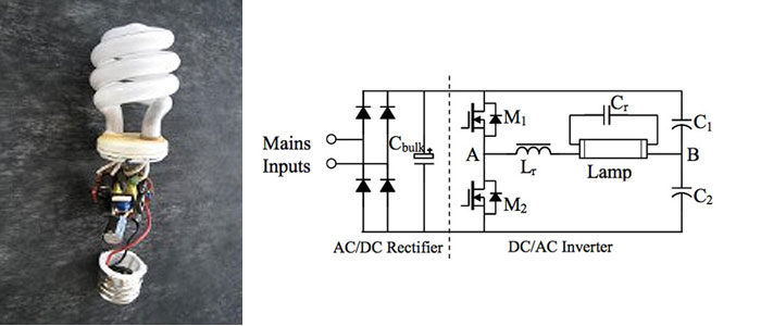
A circuit diagram for a 40W, 230V transistor-based electronic ballast is required. What steps are involved in designing an electronic ballast? An electronic ballast is a device used to regulate the current to fluorescent lamps and provide sufficient voltage to...
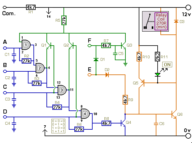
The key connected to "E" is used to energize the relay, while the four keys connected to A, B, C, and D are used to de-energize it. All other keys on the keypad are connected to "F". When "E"...
The opto-isolator LEDs are connected to three wires labeled "FWD," "REV," and "ENA." These wires serve as the interface between the bridge and the microprocessor. It is important to note that there is no "ground" signal present. When connecting...