
garageshed alarm
The burglar alarm circuit operates on a straightforward principle, utilizing a combination of resistive and capacitive components to create a timing mechanism that governs the exit and entry delays. The circuit is typically built around a timer IC, such as the 555 timer, configured in monostable mode to generate the necessary delay intervals.
The input devices, which may include magnetic reed switches or PIR sensors, are connected to the input of the timer circuit. When the system is armed, the closure of these contacts initiates the timing cycle. The timer's output can drive a relay, which in turn activates the siren when the alarm conditions are met. A green LED serves as a visual indicator, confirming the system's armed status and signaling the user during the entry delay.
The choice of resistors R5 and R6 is critical for tailoring the timing intervals. These resistors, in combination with a capacitor, define the charge and discharge times, thus controlling how long the user has to exit or enter the premises without triggering the alarm. The circuit's design allows for flexibility in component selection, ensuring compatibility with various input devices and power supply voltages, while maintaining low power consumption for extended battery life.
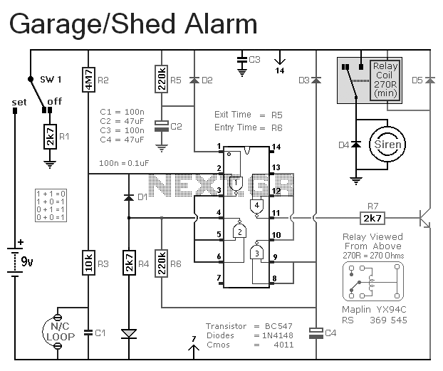
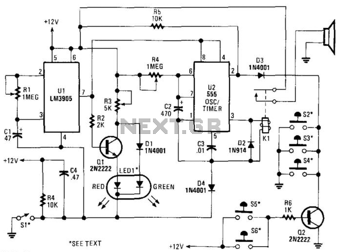
Overall, this burglar alarm circuit offers a simple yet effective solution for enhancing security in residential or commercial settings, with customizable features to meet specific user needs.This is a simple single-zone burglar alarm circuit. Its features include automatic Exit and Entry delays. It`s designed to be used with the usual types of normally-closed input devices such as - magnetic-reed contacts - micro switches - foil tape - and PIRs. It has an extremely small standby current - making it ideal for battery-powered operation. I`ve used a 9-volt battery in the diagram - but the circuit will work at anything from 5 to 15-volts. Just choose a relay and Siren suitable for the voltage you want to use. It`s easy to use. To set the alarm move SW1 to the "set" position. You now have about 10 to 15 seconds to leave the building. When you return and open the door - the green LED will light. You then have about 10 to 15 seconds to move SW1 to the "off" position. If you fail to do so - the relay will energize and the Siren will sound. Of course - you can turn the Siren off at any time by moving SW1 to the "off" position. Because of manufacturing tolerances - the precise length of any delay depends on the characteristics of the actual components you`ve used in your circuit.
But by altering the values of R5 & R6 you can adjust the Exit and Entry times to suit your requirements. Increasing the values increases the time - and vice-versa. 🔗 External reference
Related Circuits
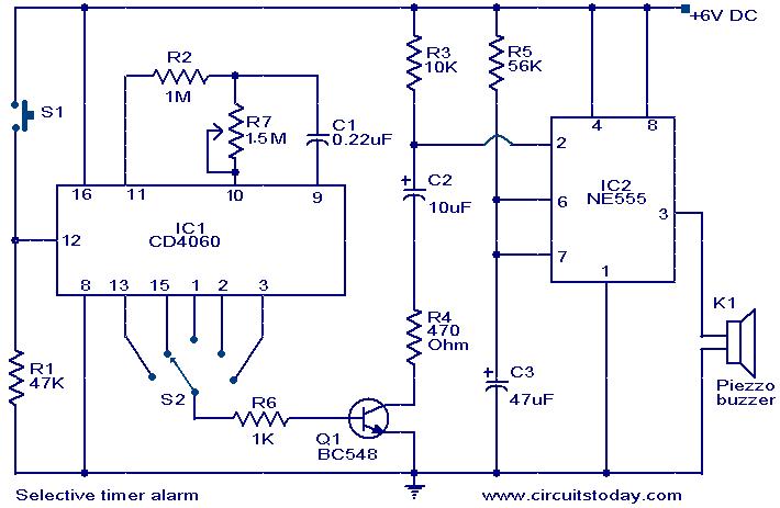
A timer circuit utilizing the IC 4060 is presented. The IC 4060 functions as a 14-stage binary counter equipped with an integrated oscillator. The components R2, R7, and C1 are responsible for determining the oscillator's frequency, causing the outputs...
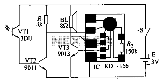
After the gas stove ignition, closing switch S, the circuit is operational. The phototransistor VT1, exposed to flame, remains in a low resistance state. This causes transistor VT2 to enter saturated conduction. Transistor VT3 and the integrated circuit (IC)...
Rain Alarm. This circuit activates an alarm when its sensor comes into contact with water. It utilizes a 555 astable multivibrator. The rain alarm circuit operates on the principle of detecting moisture through a sensor that can be designed using...
The MAXQ3210 is a powerful RISC microcontroller. This device has features and capabilities that make it suitable for battery-powered applications that require detection. The MAXQ3210 microcontroller is designed with a focus on low power consumption and efficiency, making it particularly...
Simple construction, reliable operation, very small power consumption, and, most of all, small size. I started with CMOS logic gates, but was soon forced to abandon the concept after a few unsuccessful (and far too complicated) attempts. Then I...
SI is an external key switch. The alarm allows a delay of 0 to 45 seconds after SI is operated before the circuit is armed. During this period, LED1 lights up green. After this delay, LED1 lights red, indicating...