
Car Ice ararm circuit
The circuit operates based on the principle of temperature sensing through the thermistor, which exhibits a change in resistance with temperature variations. The LM3900 quad op amp IC is utilized for its versatility, allowing for multiple configurations within a single package. The first op amp (op amp I) serves as a comparator, measuring the thermistor's resistance against a known reference resistance. This comparator output is crucial for determining the temperature threshold at which the LED indicator will respond.
The second op amp (op amp II) is configured as a free-running multivibrator, generating a square wave signal at a frequency of approximately 1 Hz. This signal is essential for providing a time-based reference to op amp III, which compares the output from op amp I with the periodic signal from op amp II. When the temperature drops sufficiently, causing the output of op amp I to fall below the level of the multivibrator's output, op amp III activates the LED, signaling a critical temperature condition.
The calibration process is vital for ensuring accuracy in temperature detection. By placing the thermistor in a controlled environment of crushed ice and water, the resistance can be accurately measured and adjusted using the 20 kΩ potentiometer. This adjustment ensures that the LED indicator functions correctly at the desired temperature thresholds, providing a reliable visual indication of temperature changes.
Overall, this circuit design exemplifies an effective application of operational amplifiers for temperature monitoring, combining analog signal processing with straightforward calibration techniques to deliver a functional and user-friendly temperature indicator.The circuit uses a thermistor and three sections of a LM3900 quad op amp IC. When the temperature drops to 36°F the LED indicator flashes about once each second. The flashing rate increases as temperature drops to 32°F when the LED remains on. Amplifier I compares the thermistor's resistance to the resistance of the standard network connected to its noninverting input. Its output—fed to the noninverting input of op amp III—varies with temperature. Op amp is a free-running multivibrator feeding a pulse signal of about 1 Hz to the inverting input of op amp III. This amplifier compares the outputs of op amps I and II and turns on the LED when the multivibrator's output level drops below op amp I.
The monitor is calibrated by placing the thermistor in a mixture of crushed ice and water and adjusting the 20 kfi pot so the LED stays on. 🔗 External reference
Related Circuits

Alarm system designs often require circuitry that can detect whether a phone line is active or broken. The primary challenge in this design is to draw less than 5 µA from the phone line, which operates within a voltage...

This circuit utilizes the Mitsubishi M65830 Digital Delay chip, which has proven to be simple and effective for applications requiring a fixed delay. The serial data necessary for achieving various delay settings is not readily available and would significantly...
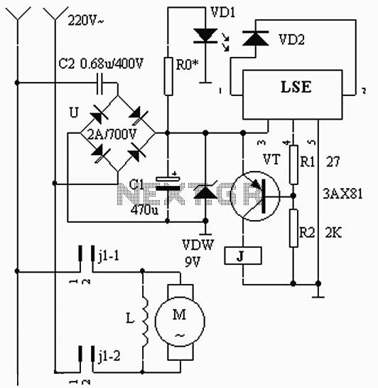
The circuit operates based on the interaction between an infrared light-emitting diode (VD1) and an infrared receiver diode (VD2). When VD1 emits infrared radiation, it is detected by VD2, which causes a decrease in its internal resistance. This change...
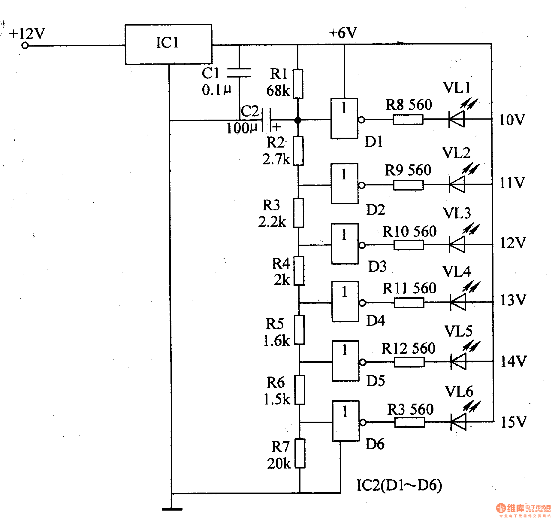
The LED car voltmeter comprises a filter circuit, a voltage distribution filter circuit, a voltage amplifier circuit, and an LED display circuit, as illustrated in Figure 7-77. The regulator filter circuit includes a 3-terminal IC (IC1) and a filter...
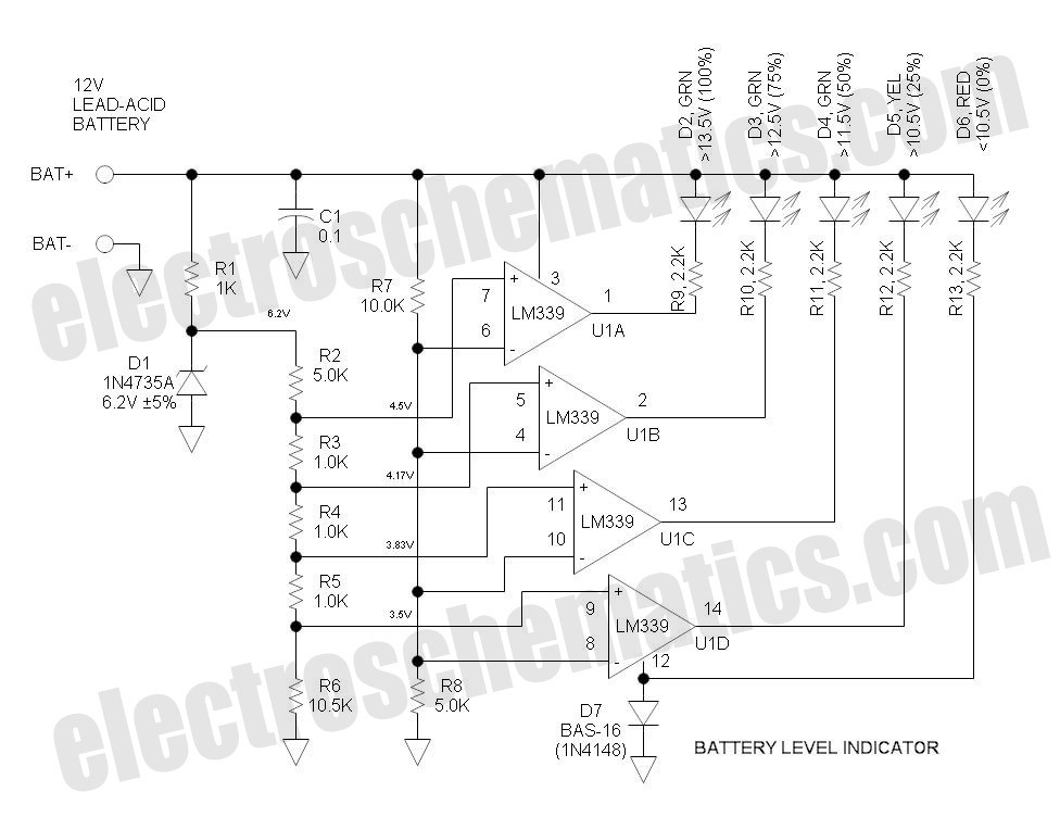
This battery level indicator features five LEDs that illuminate progressively as the voltage increases: Red indicates power connection (0%), Yellow signifies voltage greater than 10.5V (25%). The battery level indicator circuit utilizes a series of five light-emitting diodes (LEDs) to...
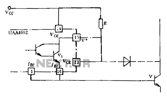
Anti-saturation devices have been removed from the UAA4002 routine applications. The base current of the switching transistor, which is driven by another transistor, is automatically adjusted. This adjustment allows the power transistors to operate in critical saturation. However, when...