
Gas stove flame alarm circuit
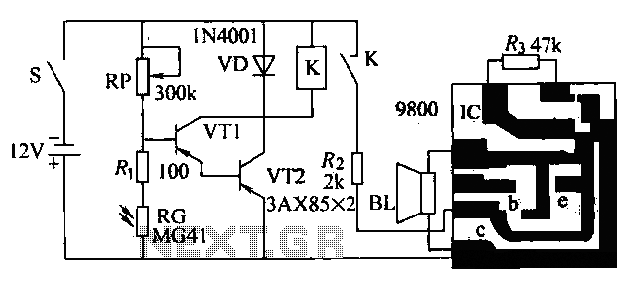
The second-generation flame alarm circuit for natural gas stoves is designed to enhance safety by detecting the presence of flame during operation. The circuit operates by monitoring the light emitted from the flame through a photoresistor (RG). When the stove is ignited, RG's resistance decreases due to the light, allowing current to flow through transistors VT1 and VT2. This conduction keeps relay K engaged, maintaining the normally closed contact in an open state and preventing the alarm from sounding.
In the event that the flame is extinguished, the light on RG diminishes, leading to an increase in resistance. This change results in the cutoff of the current to VT1 and VT2, causing relay K to disengage. The normally open contact K then closes, supplying power to the integrated circuit (IC) that drives the alarm system. The activation of the speaker (BL) produces a sound to alert the user, prompting immediate action to close the gas valve and prevent potential hazards.
The choice of components is critical for the reliability of the circuit. The JRX-13F relay is selected for its compact size and 12V operation, which is suitable for most household applications. The transistors used, such as the 9014, are readily available and can handle the necessary current for the application. Alternative transistors like 3DG4M, 3DG201, 3DG401, and 3DG8A provide flexibility in component sourcing while maintaining circuit performance.
Furthermore, the presence of an adjustable potentiometer (RP) allows for fine-tuning of the alarm's sensitivity, enabling customization based on the specific environmental conditions or user preferences. This feature enhances the effectiveness of the alarm system, ensuring that it responds appropriately to flame presence or absence. Overall, this flame alarm circuit is a critical safety device that effectively monitors gas stove operation, providing timely warnings to prevent accidents.The circuit shown is the second natural gas (gas) stove flame alarm. After the gas stove ignited normal combustion, close the power switch S. Photoresistor RG due to irradiation by light flame, its resistance is small, the transistor VT1 and VT2 conduction, the relay K pull its normally II1 contact K off, music Manifold IC does not sound. But once the gas stove flame, RG by light irradiation greatly reduced, the resistance increases, the Vri and VTZ off, the relay K to release, normally open contact K is closed, automatically turn on the power IC's source, lC work, the speaker BL Music issued warning to remind the main person close the gas valve.
In addition to the circuit has been noted, a small relay selection JRX-13F, operating voltage of 12V. Transistor VT3 to 9014, available 3DG4M, instead of 3DG201,3DG401 or 3DG8A, B and so on. Adjustment potentiometer RP, can change the alarm sensitivity.
Related Circuits

The circuit depicted in Figure 3-200 (a) illustrates the operation of a reverse braking system. When reverse braking is initiated, the forward contacts of contactor KMi open, and the reverse brake contactor KM3 disconnects while the reverse contactor KM2...
The circuit consists of an ultrasonic transmitter and a receiver that operate at the same frequency. Ultrasonic piezoelectric transducers serve as the output and input devices, respectively, with their frequency of operation determined by the specific devices used. The...
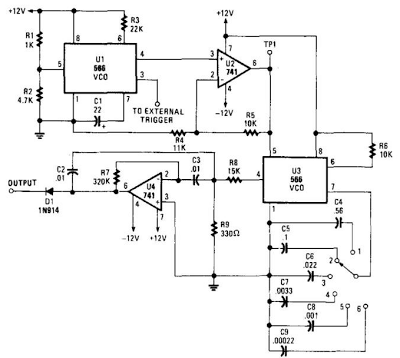
When this circuit is connected to a filter and an oscilloscope, the oscilloscope displays the filter's frequency response. A frequency that sweeps from low to high is applied to a filter. The oscilloscope is triggered by the start of...
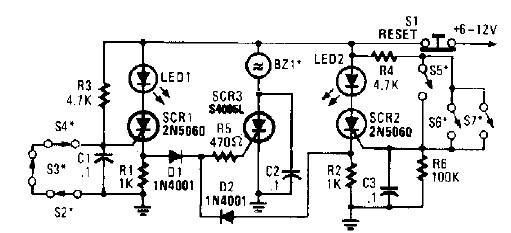
A straightforward high-power alarm driver electronic project can be developed using this circuit diagram. This high-power alarm driver project utilizes a low-power SCR to trigger a high-power SCR. When switches S2, S3, or S4 are opened or switches S5,...

This circuit consists of two main components: a battery charger that provides a fixed output voltage of 5V DC, and a regulated power supply that allows for an adjustable output voltage ranging from 2 to 9 volts. The circuit design...
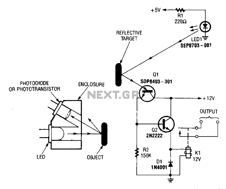
A reflex isolator detects the presence of an object by reflecting light from the object back to the sensor. This technique is effective when an object is in close proximity to the sensor. Reflex isolators, also known as proximity sensors,...