Gate Alarm
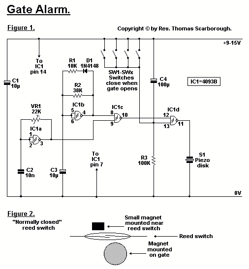
Figure 1 represents a cheap and simple Gate Alarm, that is intended to run off a small universal AC-DC power supply. IC1a is a fast oscillator, and IC1b a slow oscillator, which are combined through IC1c to emit a high pip-pip-pip warning sound when a gate (or window, etc.) is opened. The circuit is intended not so much to sound like a siren or warning device, but rather to give the impression: "You have been noticed.
The Gate Alarm circuit is designed to provide an audible alert when a gate or window is opened, utilizing a dual-oscillator configuration for sound generation. The primary components include a small universal AC-DC power supply that converts mains voltage to a suitable low voltage for the circuit operation, typically in the range of 5V to 12V.
IC1a serves as a fast oscillator, generating a rapid square wave signal that produces a high-frequency tone. This is achieved through a configuration of resistors and capacitors that define the frequency of oscillation. The output from IC1a is then fed into IC1c, which acts as a mixer or combining stage.
IC1b operates as a slow oscillator, producing a lower frequency signal that complements the output of IC1a. This combination of fast and slow oscillations creates a distinctive "pip-pip-pip" sound pattern, which is more subtle than traditional alarm sounds, aiming to alert individuals without causing undue alarm.
When the gate or window is opened, a mechanical switch or sensor is activated, providing a signal to the oscillators. This triggers both IC1a and IC1b, causing the combined output to be sent to a small speaker or piezo buzzer, which converts the electrical signals into audible sound.
The circuit design emphasizes simplicity and cost-effectiveness, making it accessible for home security applications. The choice of components ensures that the Gate Alarm remains functional with minimal power consumption, allowing it to operate efficiently from the AC-DC power supply. Additionally, the sound pattern is designed to convey a message of awareness rather than an aggressive warning, making it suitable for various environments.Figure 1 represents a cheap and simple Gate Alarm, that is intended to run off a small universal AC-DC power supply. IC1a is a fast oscillator, and IC1b a slow oscillator, which are combined through IC1c to emit a high pip-pip-pip warning sound when a gate (or window, etc.) is opened.
The circuit is intended not so much to sound like a siren or warning device, but rather to give the impression: "You have been noticed. 🔗 External reference
