
Get Negative Rail With Cmos Gates

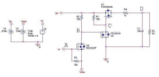
The described circuit employs a charge pump configuration, which is a type of DC-DC converter that generates a higher or lower voltage from a given input voltage by utilizing capacitors to store and transfer charge. The 7 kHz oscillator serves as the driving clock signal that controls the switching of the charge pump circuit.
When the oscillator output is high, capacitors C and D are connected in such a way that capacitor CI is grounded on its positive terminal. This action allows the circuit to create a negative voltage at the Vs terminal of U2, which can be used for various applications requiring a negative supply voltage.
The output ripple, which is an important parameter in power supply design, depends on the values of capacitors C, CI, and C2. The peak-to-peak ripple voltage can be calculated based on the switching frequency and the load current, ensuring that the output remains stable under varying load conditions.
The output impedance of the converter is approximately 100 ohms, indicating that it can effectively drive loads without significant voltage drop under normal operating conditions. The maximum current output capability is specified at 10 mA DC, making this circuit suitable for low-power applications where a negative voltage is required.
Overall, this circuit design is efficient for generating a negative voltage supply from a positive voltage source, and its performance can be optimized by selecting appropriate capacitor values and ensuring that the oscillator operates reliably at the specified frequency. Using a charge pump and oscillator, this circuit uses a 7-kHz oscillator. When the clock is high, C and D are on, grounding the positive side of CI and making negative voltage available at the Vs$ terminal of U2. With C— Ci + C2, the p-p output ripple is: Converter output impedance is about 100 and maximum current is 10 mA dc.
Related Circuits
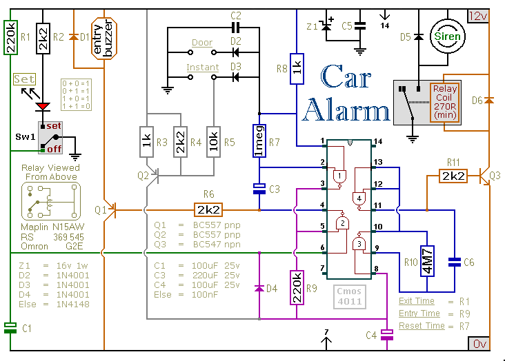
This car alarm circuit includes exit and entry delays, an instant alarm zone, an intermittent siren output, and automatic reset. By incorporating external relays, it is possible to immobilize the vehicle and activate the flashing lights. The car alarm circuit...
The idea is simply to turn off the negative voltage load. Some examples: - Bias voltages for LCD panels - RF Amplifiers - Audio Amplifiers The good thing about this design is that I can make use of the system...
Ions are defined as electrically charged atoms. Positively charged ions have a deficiency of electrons, and negatively charged ions have a surplus of electrons. An ion can also be classified as an atom or molecule with an electrostatic charge....
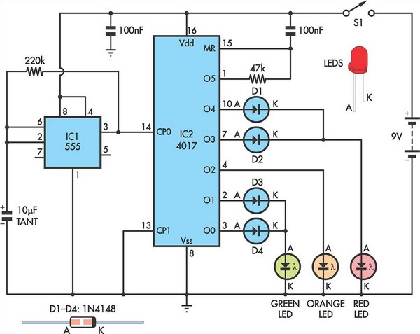
Children today often possess a wide array of toys available in stores. For those with a son or grandson who has a collection of toy cars, a handmade gift such as a set of traffic lights would be greatly...
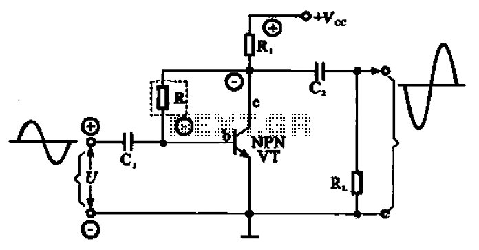
A common series negative feedback amplifier is depicted in this configuration. In this amplifier, R acts as the resistor for the negative feedback element, which is part of the input circuit. The output circuit is linked to both the...
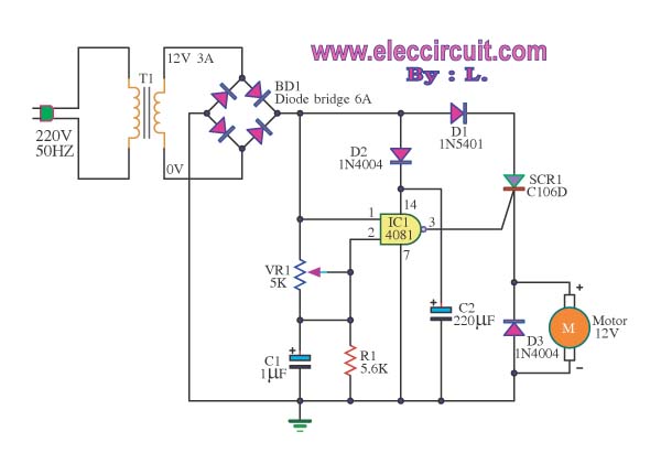
This is a speed motor controller circuit for a 12V DC motor. The speed of rotation of the spindle motor can be adjusted from 5 to 60 cycles per minute. The speed motor controller circuit for a 12V DC motor...