
Getting started with AVR development
The construction of a DIY programmer, specifically the SI-Prog, is an effective way to utilize existing components to create a functional programming tool for AVR microcontrollers. This programmer interfaces with a PC via a DE-9 connector, which connects to the serial port, allowing for straightforward communication between the PC and the microcontroller. The programmer's design incorporates a six-way pin socket for in-circuit programming, which facilitates easy connections to the microcontroller's programming header.
For programming the ATmega168, the circuit must connect to specific pins: RESET, MOSI, MISO, SCK, VCC, AVCC, and GND. These connections enable the programmer to supply power and communicate with the microcontroller. Proper pin alignment is crucial, as the pin headers can be inserted incorrectly, leading to unreliable connections. Adjustments can be made to ensure that the pins fit securely within the breadboard or circuit board.
Once the hardware setup is complete, the PonyProg software is used to load and write programs to the microcontroller. Configuring PonyProg involves selecting the correct serial interface and COM port, followed by probing to verify connectivity. After successful communication, the microcontroller's memory can be read, typically showing a blank state of 0xFF.
The development of a simple LED flashing program serves as an introductory project. This program demonstrates the basic functionality of the microcontroller and the programming process. AVR Studio IDE provides an integrated environment for writing and simulating the program. The project setup involves selecting the ATmega168 as the target device and configuring the I/O pins for the desired functionality.
The ATmega168's port registers allow for control over the digital I/O pins. By configuring the appropriate data direction registers and setting the output levels, the programmer can control the state of the connected LED. The provided C code illustrates how to toggle the LED on and off in an infinite loop, with a delay implemented to control the flashing rate.
Upon building the project, the resulting hex file can be loaded into PonyProg for programming the microcontroller. The use of command-line tools like avrdude can enhance the efficiency of the programming process, especially for iterative development. Care should be taken when modifying fuse settings, as incorrect configurations can lead to permanent changes in the microcontroller's behavior. The CKDIV8 fuse setting, for example, alters the clock frequency, affecting the timing of the LED flashing.
Overall, the DIY approach to creating an AVR programmer provides a cost-effective solution for those interested in microcontroller programming while gaining hands-on experience with electronics.You can buy ready-made programmers, but why spend money when you can build it yourself from parts that you have lying around The simple SI-Prog doesn`t require that many parts and is supported by several popular pieces of software. The full SI-Prog is designed to work with a variety of different chip types, as well as provide power to the microco
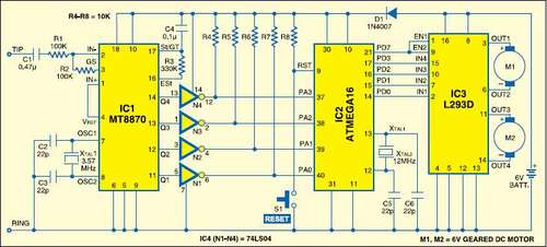
ntroller that it`s programming. If one assumes that we`re only going to be programming AVRs and powering the circuit ourselves then it can be simplified quite considerably! I`m using the circuit from the AVR Programmer page on Electronics-DIY. com. The circuit diagram is replicated below. The DE-9 connector plugs into your PC`s serial port, and so should be a standard female connector. For the in circuit serial programmer (ICSP) side, I recommend using a six-way single row pin socket - you can then put a matching pin header on your circuit board (or plugged into your breadboard) to allow you to quickly and easily connect and disconnect the programmer.
The nearest-sized sockets and headers I found were eight-way, but you should be able to cut them to size with a sharp pair of wire cutters. Now that you have a programmer, you need some way to test it. A suitable circuit for the ATmega168 is illustrated below: the programming header is connected to the AVR`s RESET (1), MOSI (17), MISO (18) and SCK (19) lines, as well as its power supply ” both VCC (7) and AVCC (20) are connected, as well as GND (7).
Consult the ATmega168 data sheet for more pin definitions. The pins in pin headers usually have one long end and one short end either side of the insulating block. You may find that they spring out of breadboards if you put the short end in first, or fail to make a proper connection to the programming header if you put the long end in first.
To even them out, you can slot the short ends into the breadboard and very carefully push the tops of the pins against a flat, hard surface ” they can be pushed through the insulating block, but make sure that you don`t bend them! Once you have built the circuit, download and install PonyProg. This is a free, easy-to-use GUI program that can be used to program the AVR. The first time you run the application, it will prompt you to configure it ” click OK on the two dialog boxes.
Click Setup, Interface Setup. Keep the Serial option button marked, and leave the drop-down box on SI Prog API. Select the COM port that your programmer is connected to from the option buttons ” if your COM port has a name above COM4 you will need to reassign it in Windows Device Manager. Leave the four polarity checkboxes unticked, then click Probe ” if all is well, a Test Ok message will be dispayed.
When it has finished reading you should receive an affirmative message, followed by a display of the AVR`s program memory. A blank AVR will read back 0xFF for every byte of program memory ” it would be nice to use the programmer to put something useful in there instead.
A simple "Hello World" program for a microcontroller could be to flash an LED connected to one of its output pins on and off. This section will take you through writing such a program. AVR programs can be written in C using free tools. One of the easiest ways to get started is to use the AVR Studio IDE (registration required) along with the WinAVR suite.
Download and install both tools ” I installed AVR Studio before WinAVR, and didn`t need to perform any additional configuration afterwards. When you start AVR Studio, it will prompt (by default) whether you`d like to create a new project or open an existing one.
If you had previously switched this dialog off, you can access it via the Project, Project Wizard menu. Start by creating a new project. When you click Next you will be prompted to select a debug platform and device. In the absence of a hardware debugger, select AVR Simulator 2 with ATmega168 as the device. This will allow you to simulate your program within the AVR Studio IDE. Finally, click Finish and your new project will be displayed with a blank source file. The ATmega168 arranges its I/O pins into ports. Each port has up to eight digital I/O pins. Some of these pins have special functions (for example, the pins we`re using to program the AVR ” MOSI, MISO and SCK ” are all in port "B") but can generally be used as input or output pins with optional interal pull-up resistors.
Each port has three associated registers. PORTxn: if the pin is configured as an output, this sets the output level ” a 0 drives the pin low, a 1 drives the pin high. If the pin is configured as an input, setting this to 1 enables the internal pull-up resistor; a 0 disables the internal pull-up.
On reset, the DDxn and PORTxn registers are set to 0. This means that initially all pins are inputs with the pull-up resistor disabled ” they float, in other words. As an example, suppose you wanted to drive pin 28 on the ATmega168 high. This would require configuring it as an output (DDxn) and setting its output level to a 1 (PORTxn). According to the ATmega168 datasheet, pin 28 is PC5 ” it is represented by the fifth bit in the port "C" registers.
To set it to be an output you would therefore need to set bit 5 in DDRC and to drive it high you would also need to set bit five in PORTC. Rather than using pin 28, I`ve chosen to use the more accessible pin 14, which turns out to be PB0. Connect an LED between the pin and ground via a 470 © current-limiting resistor. Using the above information about the I/O port registers, the code is a rather simple bit of C: #include
h> /* IO port definitions. */ #include
You can remove the warning by explicitly setting the clock speed which ” by default ” is 1MHz. To set this, click Project, Configuration Options and typing 1000000 into the box marked Frequency. PonyProg does program quite slowly, and it can be a hassle to navigate a GUI to reflash the microcontroller each time. The command-line AVR programming utility avrdude will have been installed with the other tools and can speed up the development process somewhat!
Create a file named flash. cmd in your project`s directory, containing the following commands (make sure you change the COM port number and filename as approprite): These are the AVR`s fuse settings, and these control some of the low-level functionality of the chip. For example, the various CK fuses select the type of CPU clock to use ” if you wish to use an external resonator rather than the internal 8MHz RC oscillator then you would need to change these fuses according to the type of resonator and its speed.
Consult the ATmega168 datasheet before playing with these fuses, as you can lock yourself out of the chip, unable to reprogram it! Be aware that a fuse set to a 1 in the datasheet should be unticked and a fuse set to a 0 in the datasheet should be ticked in PonyProg.
If you do misconfigure the clock fuses, you may not be able to reprogram the device to correct them. If this should happen to you, build an external crystal oscillator (such as one of these designs ) and connect its output to the XTAL1 pin (9) on the ATmega168. Using a 1MHz oscillator I have been able to get the AVR running again so I could correct its fuses. One fuse to try with the flashing LED program is the CKDIV8 fuse. This divides the clock frequency by eight which, when coupled with the default 8MHz internal RC oscillator, results in the 1MHz clock speed we specified above.
If you untick the CKDIV8 box and click Write in PonyProg the LED will start flashing eight times as fast. To compensate for this in software, set the project configuration`s frequency field to 8000000, rebuild the project then reflash the microcontroller.
🔗 External reference
Related Circuits
This instructable is categorized under 13 - 18 in the National Robotics Week Robot Contest. The National Robotics Week Robot Contest encourages innovation and creativity in robotics among participants aged 13 to 18. This category represents a significant opportunity for...

To measure temperature without using a thermometer, thermocouples are a viable option. However, thermocouples require a reference temperature, typically 0°C, to determine the temperature difference between the materials of the thermocouples, which can be inconvenient for users. To address...
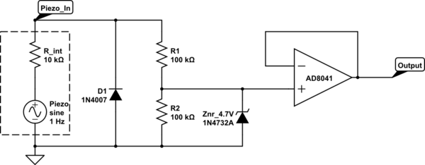
The intention is to utilize the sensor as a force sensor. It has been observed that the voltage output increases with the amount of pressure applied, although this output is only sustained for a brief period. This behavior is...
Development board for 18-pin PIC microcontrollers featuring a power supply circuit, crystal oscillator circuit, RS232 port, ICSP/ICD port, 4 relay outputs, and 4 optocoupler isolated inputs. This development board is designed to facilitate the prototyping and testing of applications utilizing 18-pin...

Designing a controller PCB for a 10x10 white LED matrix clock based on an ATmega328 AVR IC and a Maxim DS3234 SPI RTC. The challenge lies in controlling a custom non-standard 10x10 LED matrix. Initially, a Maxim MAX7219/7221 IC...

A Lithium Polymer Ion Battery is included with the Lilypad Development Board from SparkFun. There is an inquiry regarding whether the battery will charge when it is connected to the Lilypad Arduino while simultaneously connecting the Lilypad Arduino using...
Warning: include(partials/cookie-banner.php): Failed to open stream: Permission denied in /var/www/html/nextgr/view-circuit.php on line 713
Warning: include(): Failed opening 'partials/cookie-banner.php' for inclusion (include_path='.:/usr/share/php') in /var/www/html/nextgr/view-circuit.php on line 713