
GPS reference clock NTP server with Gentoo
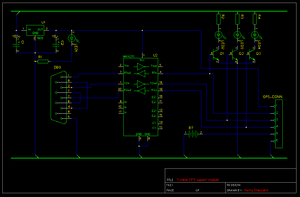
The L7805 voltage regulator is a linear voltage regulator designed to provide a stable output voltage of 5V. It is commonly used in electronic circuits where a reliable power supply is crucial. The addition of a 470µF capacitor at the input and a 10µF capacitor at the output is essential for filtering out voltage spikes and smoothing the output voltage, ensuring that the connected devices receive a steady power supply.
The MAX232 level shifter is employed to facilitate communication between devices operating at different voltage levels, such as TTL and RS-232. It converts the logic levels of the GPS module and other TTL devices to the appropriate RS-232 levels, enabling reliable data transmission. The connection of light-duty transistors to the TTL-side of the MAX232 allows for visual indication of device status through LEDs, which illuminate based on the activity of the PPS, TXD, and RXD lines.
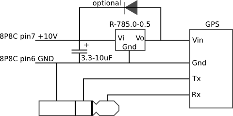
The design adaptation for the Minion chassis emphasizes compactness and integration. By eliminating the LEDs and utilizing a direct connection to the internal serial port of the EPIA MII, the circuit maintains functionality while reducing space requirements. The use of a 10-pin PCB header cable simplifies connections and improves the overall organization of the circuit.
Powering the circuit from a Molex connector ensures that the system can draw sufficient current while maintaining a neat installation. The PicoPSU's trailing cable provides a convenient power source, and the direct header connection to the regulator enhances accessibility and reduces potential wiring errors.
To enable precise PPS timing, the Linux kernel must be patched appropriately. The described steps for preparing the kernel involve moving existing directories, creating symbolic links to the required header files, and copying necessary documentation. This setup is critical for ensuring that the system can utilize the PPS signals effectively, which can enhance the timing accuracy for applications requiring precise synchronization. The configuration options for enabling PPS support in the kernel must be carefully selected to ensure full functionality.An L7805 provides a 5v rail. The input and output of the reg is bridged by a 470 F and a 10 F capacitor respectively to try and smooth things out a bit. The 5v rail created by the L7805 then powers the MAX232 level shifter and the GPS module itself. Thee light-duty transistors have their bases coupled to the TTL-side of the MAX232 PPS, TXD and R XD lines, which in turn drive three LEDs to give some indication that the device is doing what it should. Once the thing was proven to work, it was time to build a version small enough to squeeze along side the GPS module within Minion`s chassis.
The same basic design was employed, but this time without the LEDs: Rather than using the external serial port, I made up a 10-pin PCB header cable to attach directly to the EPIA MII`s internal serial port. Overall the effect is quite pleasing: Power is taken from the spare molex provided by the PicoPSU`s trailing cable and attaches to a header directly infront of the reg.
All in all, it has proved to be a suspiciously neat install! In order to take advantage of accurate PPS timing, the Linux kernel needs to be patched for PPS support. At the time of writing, the latest Gentoo kernel in Gentoo`s unstable branch is gentoo-sources-2. 6. 28-r2, so I`m going to work against that. The patch applied cleanly with me, so no additional fiddling around was required. Using your favourite kernel config method, make sure PPS support is enabled:
old # mv asm asm. old # mv asm-generic asm-generic. old # ln -s /lib/modules/$(uname -r)/build/include/linux linux # ln -s /lib/modules/$(uname -r)/build/arch/x86/include/asm asm # ln -s /lib/modules/$(uname -r)/build/include/asm-generic asm-generic # cp /lib/modules/$(uname -r)/build/Documentation/pps/timepps. h timepps. h 🔗 External reference
Related Circuits
The mobile rig, a Kenwood TM-D710E, required a GPS receiver for APRS use. The GPS-710 was not readily available and was quite expensive, prompting the decision to build a custom solution. A Royaltek RGM-3600 GPS receiver was purchased on...
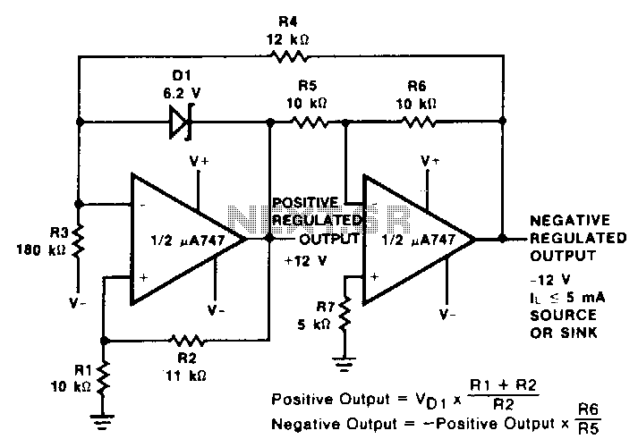
This reference utilizes an operational amplifier (op amp) to generate a negative output voltage that corresponds with the positive reference voltage. A pA747 dual op amp, or any similar device such as an LM1458 or two 1-A741 devices, can...
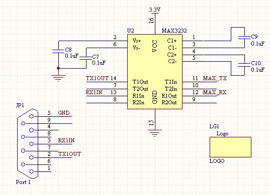
Once the setup of an RS232 connection is understood, it becomes a straightforward process for future projects. This design features a compact SMD version of the power supply, which can also be constructed using through-hole components on a breadboard....
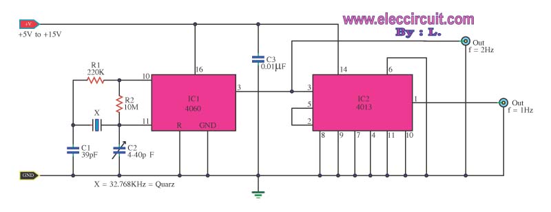
This is a standard digital clock circuit with a frequency of either 1 Hz or 2 Hz. It can be utilized in a conventional clock circuit. The circuit comprises IC-4060 and IC-4013. The digital clock circuit operates by utilizing the...
This is a simple circuit of a low-power voltage regulator reference. This circuit can produce a stable voltage reference. The low-power voltage regulator reference circuit is designed to provide a consistent output voltage, which is crucial for various electronic applications...
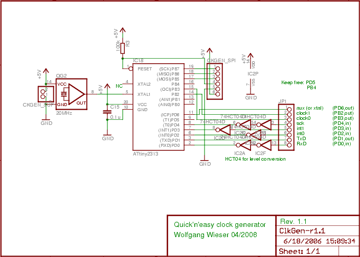
The design generates varying sampling clock write strobe pulses using an ATtiny2313 microcontroller from Atmel. For a 10MHz sampling clock, a 20MHz clock is required for the ATtiny2313, necessitating a power supply of 5V instead of 3.3V, which is...