
Wireless Coupler Terminal Interface
To further increase the transmitter's range, 220-ohm bias resistors are used. This sets the maximum peak current from the microcontroller’s output pin at about 23 milliamps, safely below the maximum current specified on the microcontroller’s data sheet. Since the antenna is resonant, the peak antenna current is greater than the microcontroller's drive current, about 70 milliamps peak-to-peak in this case.
The Base Unit uses a trick to increase the receiver's sensitivity. An adjustment is added to compensate for some of the comparator's offset. The smaller the offset voltage, the smaller the signal needed from the antenna to trip the comparator. Adjusting R1 causes the voltage drop across R3 of up to ± 60 millivolts, and this effectively compensates for offset voltages across the comparator input up to the maximum shown on the controller’s data sheet.
Increasing the sensitivity can be beneficial, but excessive sensitivity can lead to problems. When the offset is adjusted to near zero, noise from the microcontroller itself can cause the receiver to repeatedly detect false signals. Additionally, placing the base unit too close to a backlight power supply in a notebook computer may introduce interference. Not only does the RS-232 output send out corrupted data, but the noise can also interfere with the proper decoding of desired signals. The solution involves reducing the sensitivity adjustment to a level where the receiver remains stable.
The firmware for the terminal interface is compact. Its primary function is to check for incoming characters from the UART; if one is present, it sends it out via the Minimum Mass Wireless Coupler. Similarly, it checks the Minimum Mass Wireless Coupler for incoming characters and sends them out through the UART.
If an escape character is received from the terminal, the subsequent character is processed as a command. If the character following the escape character is another escape character, it is transmitted over the Minimum Mass Wireless Coupler. If the character following the escape character is an ASCII "e", local echo is toggled on and off, and a notification is displayed on the terminal screen. The "e" command is the only command recognized by this interpreter.
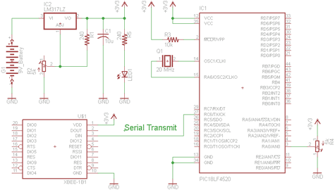
The overall design of the terminal interface and Base Unit emphasizes effective communication between a computer and devices equipped with the Minimum Mass Wireless Coupler, ensuring reliable data transmission and reception through careful consideration of component selection, circuit design, and firmware implementation. The RS-232 interface operates at a standard baud rate, while the antenna design enhances the range and performance of the wireless communication. The sensitivity adjustments and noise management strategies are critical for maintaining signal integrity in various operational environments.The purpose of the terminal interface is to allow my computer to communicate with Minimum Mass Wireless Coupler equipped devices using a terminal emulator program. Consequently, the Base Unit is basically an RS-232 interface and Minimum Mass Wireless Coupler. The Base Unit is the larger enclosure in Photo 1. The RS-232 interface to the computer is 9600 baud, 1 stop bit, no parity, plenty fast to keep up with the 1200 baud maximum data rate from the Coupler.
The antenna is made of 12 turns of #30 enameled wire threaded through metal guide loops arranged around the perimeter of the board (See the photograph.) This antenna's area is about 160% that of the prototype 5.5 cm loop so it has a little more range for both transmitting and receiving. To further increase the transmitter's range, I used 220 ohm bias resistors (See the schematic, Figure 4). This sets the maximum peak current from the microcontroller’s output pin at about 23 milliamps, safely below the maximum current specified on the microcontroller’s data sheet.
Since the antenna is resonant, the peak antenna current is greater than the microcontroller's drive current, about 70 milliamps peak-to-peak in this cae. The Base Unit uses a trick to increase the receiver's sensitivity. I added an adjustment to compensate for some of the comparator's offset. The smaller the offset voltage, the smaller the signal needed from the antenna to trip the comparator.
Adjusting R1 causes the voltage drop across R3 of up to ± 60 millivolts, and this effectively compensates for offset voltages across the comparator input up to the maximum shown on the controller’s data sheet. Increasing the sensitivity can be a good thing, but too much can be a problem. When the offset is adjusted to near zero, noise from the microcontroller itself causes the receiver to repeatedly detect false signals.
I've also noted that when I put the base unit too close to a backlight power supply in my notebook computer it picks up interference. Not only does the RS-232 output send out garbage, but the noise interferes with the desired signals from being properly decoded.
The solution is to back off on the sensitivity adjustment. to the point that the receiver is stable. The firmware for the terninal interface is very compact. All it does is to check for an incoming character from the UART if one is present, send it out the Minimum Mass Wireless Coupler, and check the Miniumu Mass Wireless Coupler for an incoming character, and if one is present, send it out the UART. If an escape character is received from the terminal, the following character is trapped and executed as a command.
If the character following the escape character is a second escape character, it is sent out over the Minimum Mass Wireless Coupler. If the character following the escape character is an ASCII "e", local echo is toggled on and off, and a notation is typed to the terminal screen.
The "e" command is the only command that this interpreter responds to. 🔗 External reference
Related Circuits
This article continues the AT90S4433 Microcontroller series. It is recommended to read the previous articles on Atmel Microcontroller programming. This time, a frequency counter is designed to measure frequencies from 1Hz to 100MHz. Alternatively, it can be used to...
There are two schematics to examine for constructing a transmitter/receiver system. The first schematic is the transmitter, featuring a variable trimpot connected to RA0. The trimpot's value will be transmitted from the Tx pin of the PIC to the...
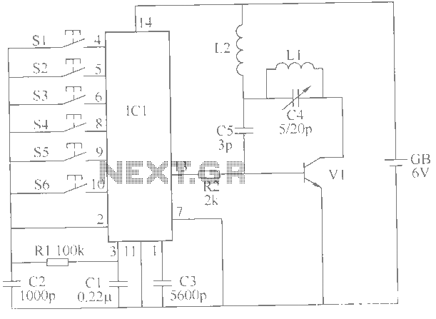
This example describes a wireless remote control switch featuring reliable operation and practical characteristics, capable of remotely controlling a 6-channel device within a 6-meter range for household electricity. The wireless remote control switch circuit consists of a wireless transmitter...
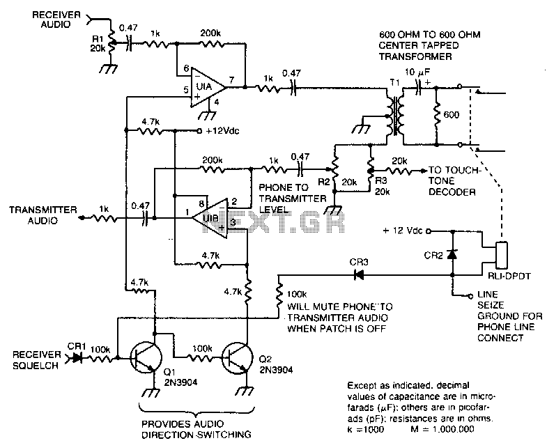
This circuit facilitates the communication link between the receiver and the phone line, as well as the phone line and the transmitter, utilizing an operational amplifier (op-amp) for signal amplification. The described circuit connects a receiver to a phone line...
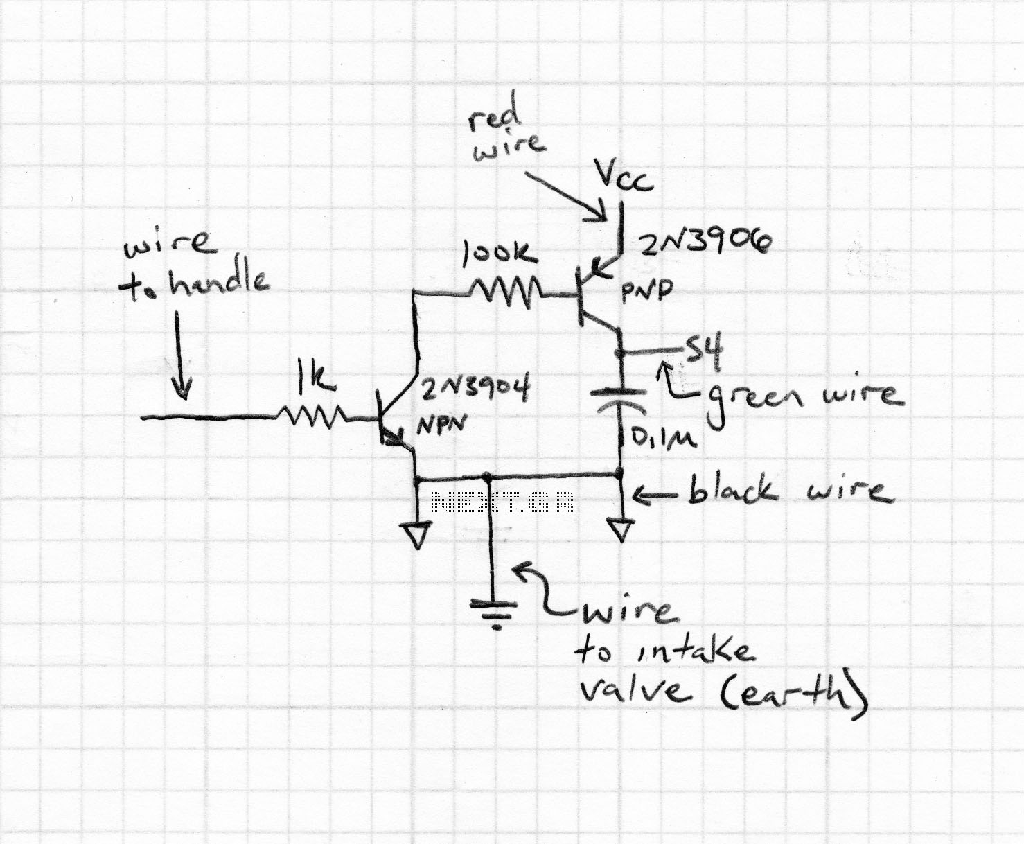
Prototype 2 utilizes a common base to control various elements. This iteration includes a button that activates the tone only when pressed, along with a rotary potentiometer for volume adjustment. The circuit incorporates an Analog Devices ADXL3xx accelerometer that...
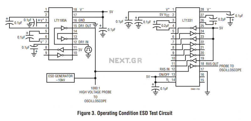
The machine model, commonly used for ESD testing in Japan, is a more severe ESD test. This model simulates metallic contact between the device under test and a charged body. The source capacitor is 200pF with no limiting resistor....
Warning: include(partials/cookie-banner.php): Failed to open stream: Permission denied in /var/www/html/nextgr/view-circuit.php on line 713
Warning: include(): Failed opening 'partials/cookie-banner.php' for inclusion (include_path='.:/usr/share/php') in /var/www/html/nextgr/view-circuit.php on line 713