
Grid DIP Meter
The circuit operates as a versatile RF measurement tool, leveraging the properties of the Colpitts oscillator to generate stable oscillations across a specified frequency range. The seven plug-in coils allow for easy frequency adjustments, making it suitable for various applications in RF testing and measurement. Each coil is designed to resonate at different frequencies, providing flexibility in tuning the circuit for specific tasks.
The coaxial socket J2 is a critical component, facilitating the connection of an external frequency meter. This feature enhances the circuit's functionality, allowing users to obtain precise frequency readings. The Teflon formers used for the coils contribute to the circuit's performance by minimizing dielectric losses, which is essential for maintaining signal integrity at higher frequencies.
Transistor TR2 serves a dual purpose in the circuit. As a DC amplifier, it boosts the output signal to a level that can be displayed on the 1 mA FSD meter, which is a standard instrument for measuring low currents. The sensitivity control provided by resistor R7 allows the user to calibrate the meter according to the application, ensuring accurate readings across different signal strengths.
The inclusion of switch S2, which controls TR1, introduces an additional mode of operation. When TR1 is deactivated, the circuit transitions to a field strength meter or RF sniffer mode. This functionality is invaluable for detecting and measuring the strength of RF signals in a given environment, making the circuit a practical tool for RF engineers and hobbyists alike.
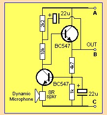
Overall, this circuit exemplifies a well-designed RF measurement instrument that balances versatility, accuracy, and ease of use, making it suitable for a range of applications in the field of electronics and radio frequency engineering.This circuit was developed by Luigi Falcone, I1FLC. He uses seven plug in coils covering 3. 0 to 30Mhz in a Colpitts oscillator circuit. The coaxial socket J2 permits connection to a frequency meter when required. The coils are wound on Teflon formers with two "female" sockets which plug-in to two "male" sockets on the instrument. TR2 forms a DC am plifier permitting the use of a 1mA FSD meter with sensitivity controlled by R7. With TR1 switched off (via S2) the instument forms a field strength meter/ RF sniffer. 🔗 External reference
Related Circuits
This is a circuit schematic diagram for VU meters. The circuit is controlled by the IC TL072 and follows a measurement circuit as per the National general application. The input circuit around IC1 is designed for adaptation and amplification...
A basic digital voltmeter circuit utilizing the Harris Semiconductor ICL7107 is presented. It operates within a 2-V range. Calibration involves applying a known voltage of 1.2 V to the input and adjusting resistor R3 to achieve an accurate reading...
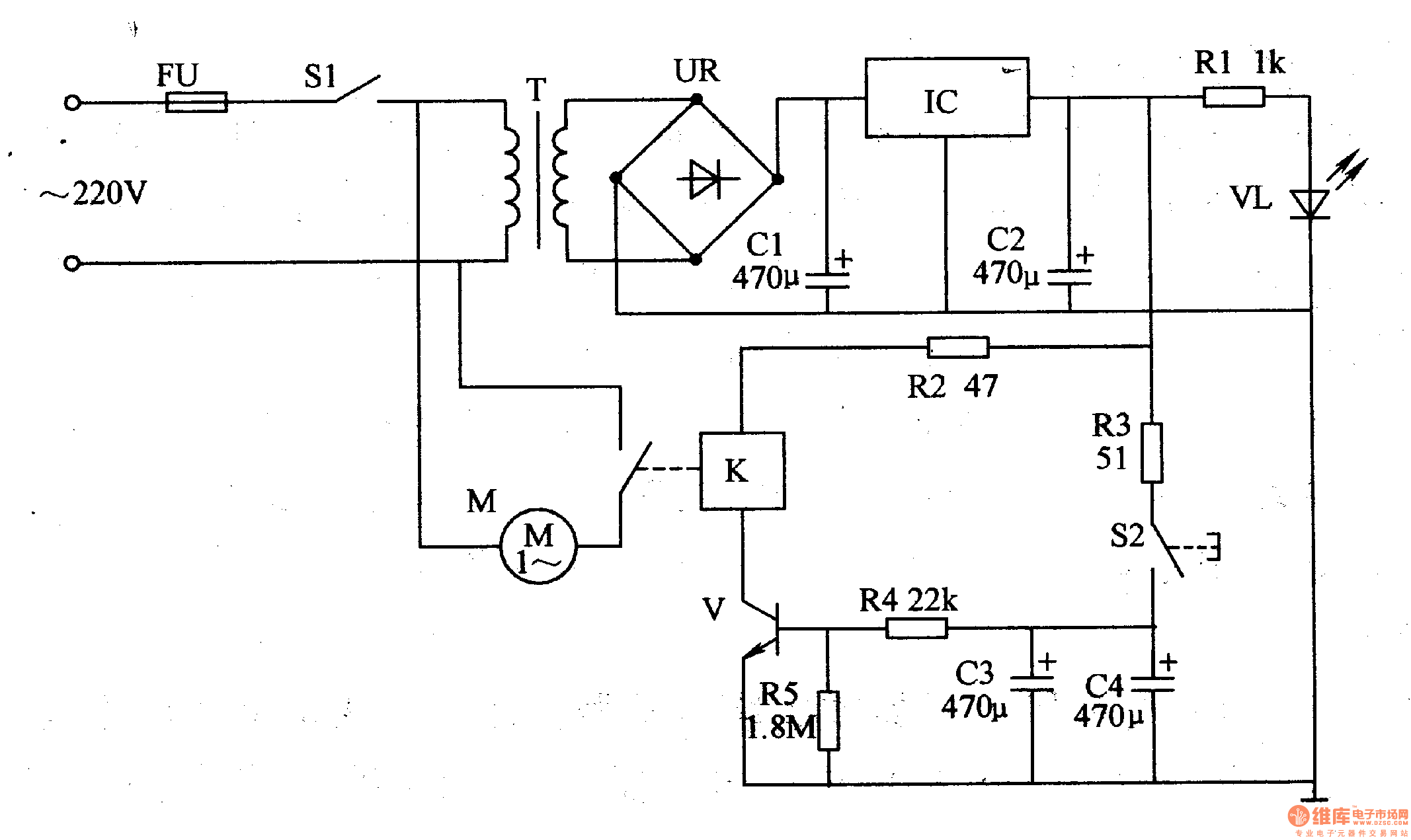
The thermometer meter slinger circuit consists of a power supply circuit and a meter slinger timing control circuit. The power supply circuit includes a fuse (FU), a power supply switch (S1), a power transformer (T), bridge rectifiers (UR), filter...
Amplifying the output from the iPod's headphone jack is necessary because the signal is insufficient for the chip to respond adequately. This situation arises from research conducted on three different chips. The LM3914 is a linearly calibrated device, meaning...
This is a stereo LED level meter. It is the most affordable and effective bar graph display available, utilizing commonly accessible components. The circuit requires only a few LEDs, 22 transistors, some resistors, diodes, and a set of electrolytic...
An Icom PCR-1000 is utilized for listening to various MF, HF, and VHF radio stations. There is a minor inconvenience related to the antennas. The K9AY antenna performs well from 500 KHz to approximately 25 MHz, while the discone...