
Thermometer meter slinger 1
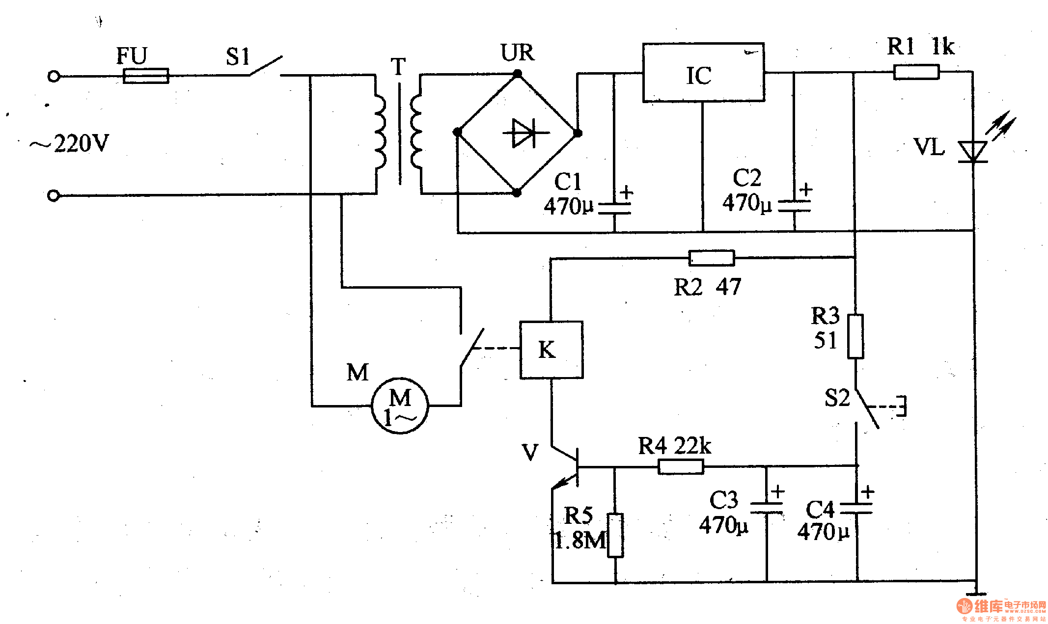
The thermometer meter slinger circuit is designed to measure temperature and provide a controlled output based on the sensed temperature. The power supply circuit is crucial for supplying the necessary voltage and current to the entire system. It begins with the fuse (FU), which protects the circuit from overcurrent conditions. The power supply switch (S1) allows for the manual control of the circuit's power state.
The power transformer (T) steps down the mains voltage to a lower, usable level. The output from the transformer is then directed to the bridge rectifiers (UR), which convert the AC voltage to DC voltage. The filter capacitors (C1, C2) smooth out the rectified DC signal, reducing ripple and providing a steady voltage output. This stable DC voltage is essential for the operation of the integrated circuit (IC), which regulates the voltage to specified levels suitable for the circuit's components.
The current limiting resistor plays a critical role in protecting sensitive components from excessive current, ensuring reliable operation of the thermometer meter slinger circuit. The timing control circuit works in conjunction with the power supply to manage the operation of the meter slinger, allowing for accurate and timely temperature readings. Overall, this circuit is integral for applications requiring precise temperature measurements and control.The thermometer meter slinger circuit is composed of power supply circuit and meter slinger timing control circuit, it is shown in the figure 9-134. The power supply circuit is made of fuse FU, power supply switch S1, power transformer T, bridge rectifiers UR, filter capacitors C1, C2, there terminals steady voltage integrated circuit IC, current limiting r..
🔗 External reference
Related Circuits
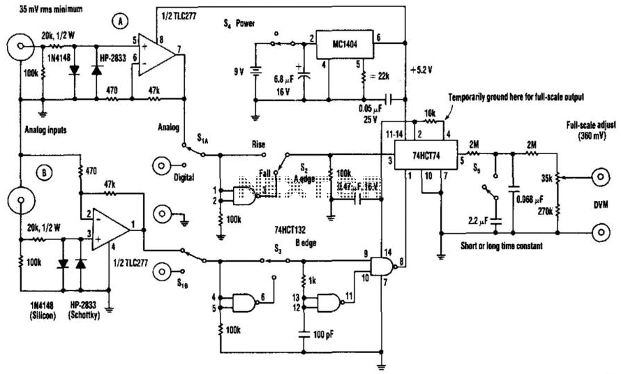
The phase-angle meter operates with both analog and digital inputs. A digital voltmeter (DVM) serves as the readout device. The output is 1 mV per degree, with a full-scale output of 360 mV corresponding to 360 degrees. The MC1404...
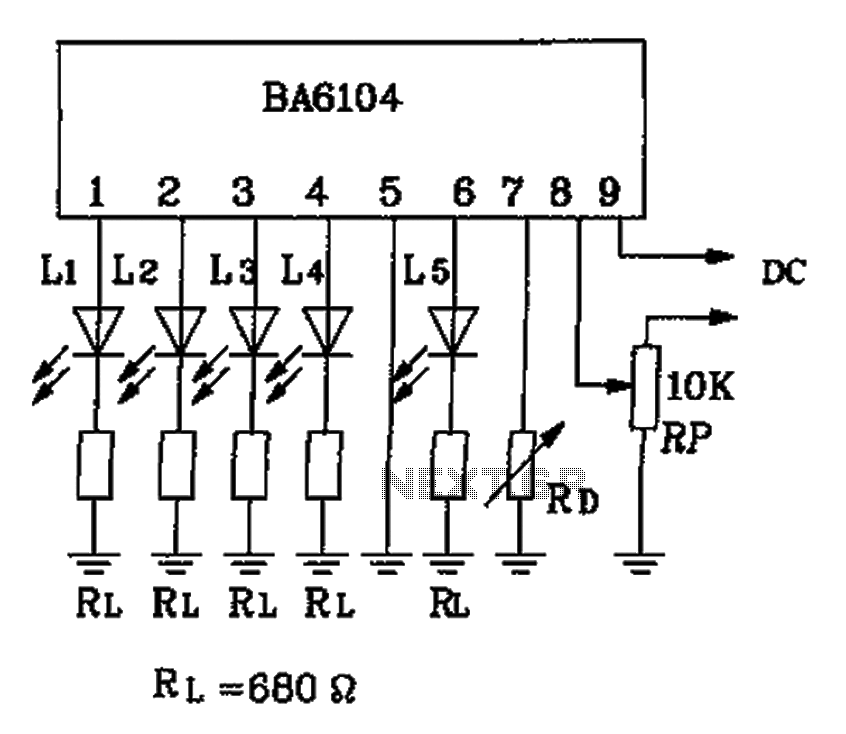
The BA6104 is a five-digit LED level meter driver integrated circuit (IC) used in basic application circuits. When the input level exceeds the required display threshold of 1V, only 7 feet of the power supply Vcc are indirectly affected...
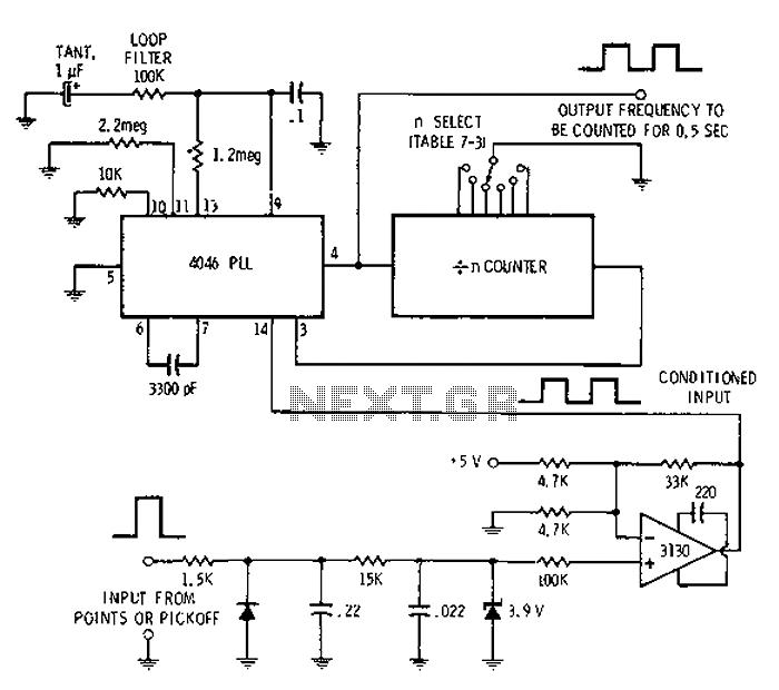
Automotive engine pulse points or other sensors are filtered using the transmission device 3130 CMOS operational amplifier, which functions as a comparator to fulfill the input conditions. The pulse subsequently flows into a 4046 phase-locked loop (PLL) N-counter, which...
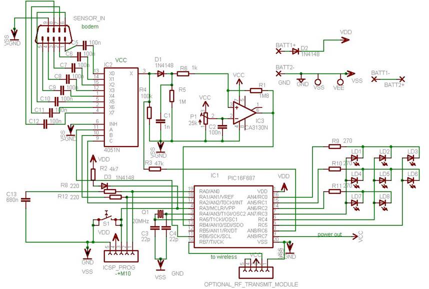
This project illustrates various features of the PIC16F687 microcontroller, including ultra-low power wake-up, serial communications, and nanowatt technology. The device can serve multiple purposes, such as measuring the water level in a rainwater tank or a water tank in...
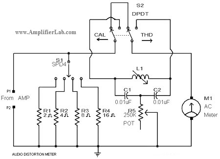
A circuit diagram of an audio distortion meter is presented here. An audio distortion meter is utilized to measure Total Harmonic Distortion (THD). The audio distortion meter is an essential tool in audio engineering, designed to quantify the level of...
When this thermometer is utilized in a room environment, it operates intermittently, maintaining this operational state within the temperature measurement circuit due to the stable internal temperature. The astable multiresonance oscillator is composed of transistors VT1 and VT2, forming...