
Battery condition indicator
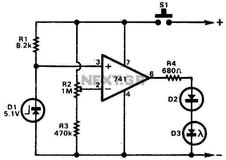
The circuit employs a 741 operational amplifier configured as a voltage comparator. The primary function of this configuration is to compare the voltage at its non-inverting input (V+) with the voltage at its inverting input (V-). The non-inverting input is connected to a zener diode, which stabilizes the reference voltage at 5V. The inverting input is set to receive half of the supply voltage through a voltage divider network formed by the resistor R2.
In operation, when the supply voltage is above 10V, the voltage at the inverting input will be 5V (half of the supply voltage), which is equal to the reference voltage at the non-inverting input. In this condition, the output of the op-amp remains low, and the LED remains off. When the supply voltage decreases below 10V, the voltage at the inverting input drops below 5V, making the non-inverting input higher than the inverting input. This condition results in the op-amp output transitioning to a high state, which activates the LED.
The design allows for flexibility in setting the threshold voltage by adjusting the value of R2. By changing R2, the voltage at the inverting input can be manipulated to create different activation points for the LED, allowing the circuit to signal different voltage levels based on the application requirements. The LED serves as a visual indicator of the supply voltage status, providing immediate feedback on the circuit's operational state. This simple yet effective design is useful in various applications where monitoring supply voltage is critical.A 741 op amp is employed as a voltage comparator. The noninverting input is connected to zener reference source. Reference voltage is 5V. R2 is adjusted so that the voltage at the inverting input is half the supply voltage. When supply is higher than 10V, the LED will not light. When the supply falls just fractionally below the 10V level, the IC inverting input will be slightly negative of the noninverting input, and the output will swing fully positive The LED will light, indicating that the supply voltage has fallen to the preset threshold level. The LED can be made to light at other voltages by adjusting R2. 🔗 External reference
Related Circuits
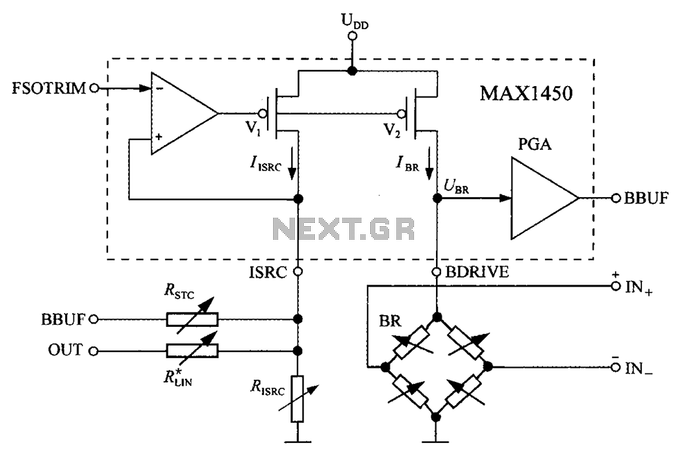
The circuit diagram for the bridge integrated pressure signal conditioner MAX1450 is composed of various components. The MAX1450 is a high-performance integrated circuit designed for signal conditioning in pressure sensing applications. It is particularly suited for use with resistive bridge...
This simple charger utilizes a single transistor as a constant current source. The voltage across the pair of 1N4148 diodes biases the base of the BD140 medium power transistor. The circuit operates by employing the BD140 transistor to regulate the charging...
Nokia BL-4C and BL-5C are 3.7V, 700-1000mAh (various) lithium-ion batteries that have three terminals. These terminals include a positive terminal, a ground, and a BSI (Battery Status Indicator) terminal, which presents a fixed resistance value that needs to be...
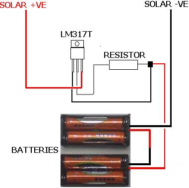
The following circuit illustrates the LM317T IC designed for a solar battery charger circuit diagram. Features include a simple circuit suitable for AA and AAA rechargeable batteries. The LM317T is a versatile linear voltage regulator that can be used in...
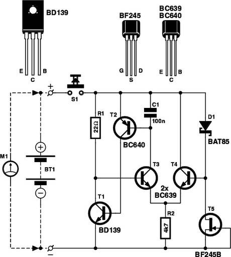
Determining whether a battery is empty or if there is a fault with a device can be challenging when a battery-powered device, such as a Walkman, fails to power on. Before seeking professional repair, it is advisable to test...
This circuit is designed to flash a white LED using a supply voltage ranging from 2V to 6V, resulting in a very bright flash. The circuit operates at approximately 2mA, allowing the use of old batteries. When powered at...