
GSM CELL PHONE JAMMER SCHEMATIC
The GSM jammer circuit operates by emitting radio frequency signals that interfere with the communication between mobile phones and base stations within the specified frequency range. The circuit typically consists of a signal generator, an amplifier, and an antenna. The signal generator produces a continuous wave signal at the desired frequency, while the amplifier boosts the power of the signal to ensure effective jamming. The antenna radiates the jamming signal, creating a zone where mobile devices cannot establish a connection with the network.
To construct the circuit, a suitable oscillator is selected to generate the frequency of interest, which can be tuned to the GSM1900 band. Common components may include a 555 timer IC for generating the oscillation, followed by a power amplifier circuit such as a transistor or an operational amplifier to increase the signal strength. The output can be connected to a dipole or monopole antenna, designed to radiate the jamming signal effectively.
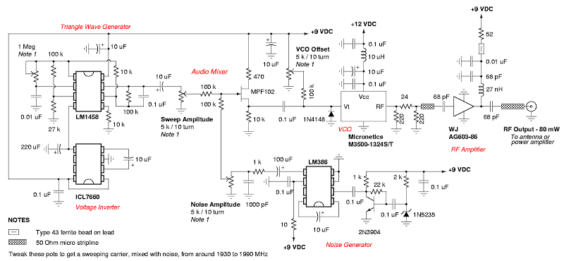
It is important to note that the use of GSM jammers is illegal in many jurisdictions, as they can disrupt legitimate communications and emergency services. Therefore, this schematic should be utilized with caution and in compliance with local laws and regulations.A wonderful diy gsm jammer or cellular mobile phone jammer schematic diagram for use only in GSM1900 with frequency from 1930 MHz to 1990 MHz. The GSM1900 cellular cell phone network is made use of by USA, Canada and most of the nations in South America.
This cellular phone jammer isn`t applicable for use in Europe, Center East, nor Asia. The GSM jammer circuit could block mobile mobile phone signals which operates on GSM1900 band, also identified as DCS. 🔗 External reference
Related Circuits
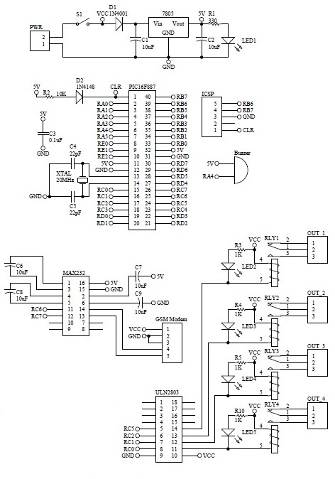
How to turn on equipment by sending SMS `1111` to switch it ON and switch off the equipment by sending SMS `0000`. The GSM switch will receive instructions for either load 1 (L1), load 2 (L2), load 3 (L3),...
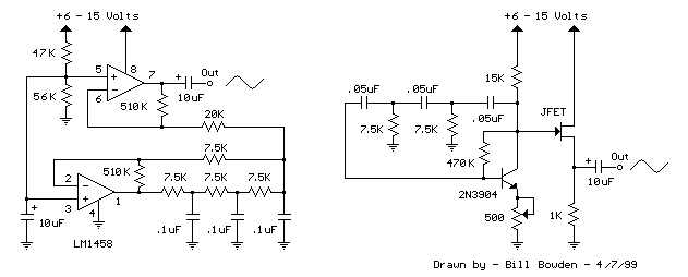
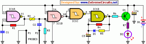
The two circuits below illustrate generating low frequency sinewaves by shifting the phase of the signal through an RC network so that oscillation occurs where the total phase shift is 360 degrees. The transistor circuit on the right produces...
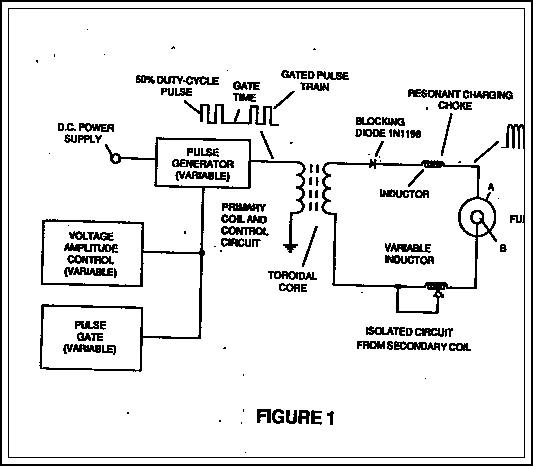
The fundamental concept involves a high-frequency, high-voltage, low-current signal that is rectified and subsequently utilized to charge a bank of high-value capacitors. These capacitors are then discharged in pulse mode for brief intervals, specifically in the nanosecond range, through...
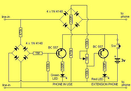
This project has two features. It will let you know when a single phone is using the line and also when two phones are on the line! The green LED indicates the first phone and the red LED indicates...
This circuit is designed to indicate when a plant requires watering. An LED blinks at a low frequency when the soil in the flower pot is excessively dry, turning off as the moisture level rises. The sensitivity of the...
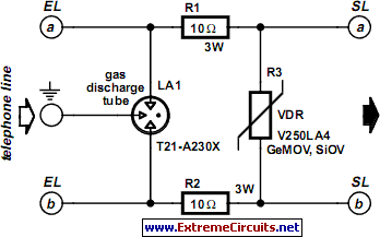
A long time ago, when telephones were simple and reliable from an electrical standpoint, telecom operators installed surge protection on all telephone lines exposed to storm risks. Ironically, this protection has diminished as more delicate and expensive equipment, such...