
How to add 32K crystal/clock source to AVR Microcontroller (ATmega8)
The Atmel AVR microcontroller Atmega8 is a popular choice for various embedded applications, often requiring an external clock source to enhance its performance and functionality. This article provides a comprehensive guide on integrating a 32KHz external crystal oscillator with the Atmega8 microcontroller.
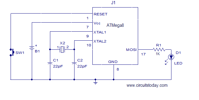
The circuit diagram typically includes the Atmega8 microcontroller, the 32KHz crystal, and two load capacitors connected to the crystal. The crystal is connected between the XTAL1 and XTAL2 pins of the microcontroller. The load capacitors are connected from each pin of the crystal to the ground. The values of these capacitors are usually selected based on the specifications provided in the crystal datasheet, often ranging from 18pF to 22pF to ensure proper oscillation.
The C program required for configuring the microcontroller to utilize the external clock source involves setting the appropriate fuse bits to select the external crystal oscillator as the clock source. This program may also include initialization routines for configuring the microcontroller's I/O ports and any peripherals that will interact with the timing provided by the 32KHz clock.
This setup is particularly useful for applications requiring accurate timekeeping, such as real-time clocks (RTCs) or low-power applications where the microcontroller can operate at lower frequencies to conserve energy. The integration of the 32KHz crystal oscillator allows the microcontroller to achieve precise timing and reliable performance in various applications.This article explains how to add 32K external crystal/clock source to Atmel AVR micro controller Atmega8 with circuit diagram & C program.. 🔗 External reference
Related Circuits
A setup was created using 22 used octal tubes, specifically 6.3-volt, 600mA controlled-warm-up tubes (predominantly 6SN7s), along with 22 octal tube sockets and an old extension cord. The sockets were wired in series and connected to a wall socket,...
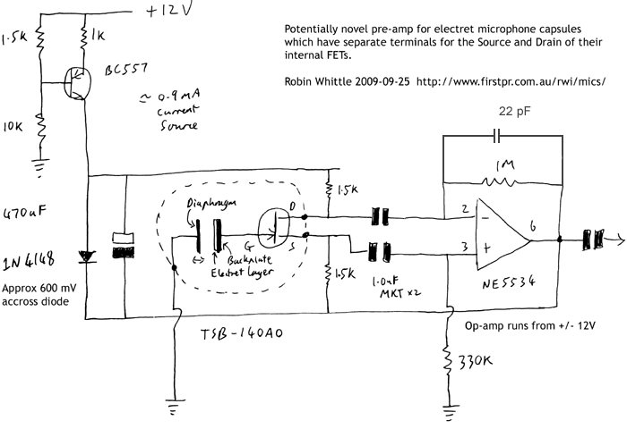
This circuit may be of interest to individuals designing preamplifiers for electret and externally polarized condenser microphones that lack an internal FET. If the noise from a single FET is a limiting factor, utilizing two or four FETs in...
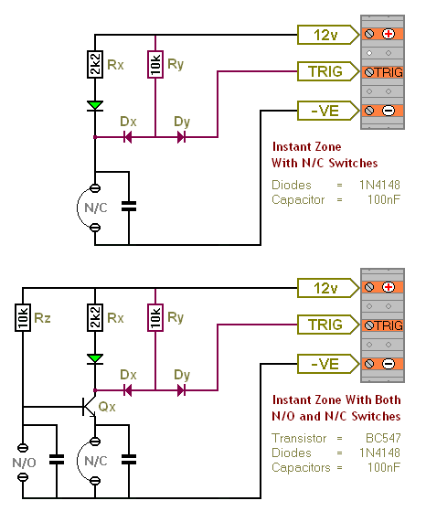
The Transistor Burglar Alarm System allows for the addition of multiple extra zones. The primary circuit is compatible with standard normally-closed input devices, including magnetic reed contacts, micro switches, foil tape, and passive infrared sensors (PIRs). An auxiliary circuit...
In 1991, there was significant interest in a specific display technology that was difficult to find locally and expensive to import. Currently, this technology has become widely available and is considered obsolete due to the affordability and accessibility of...
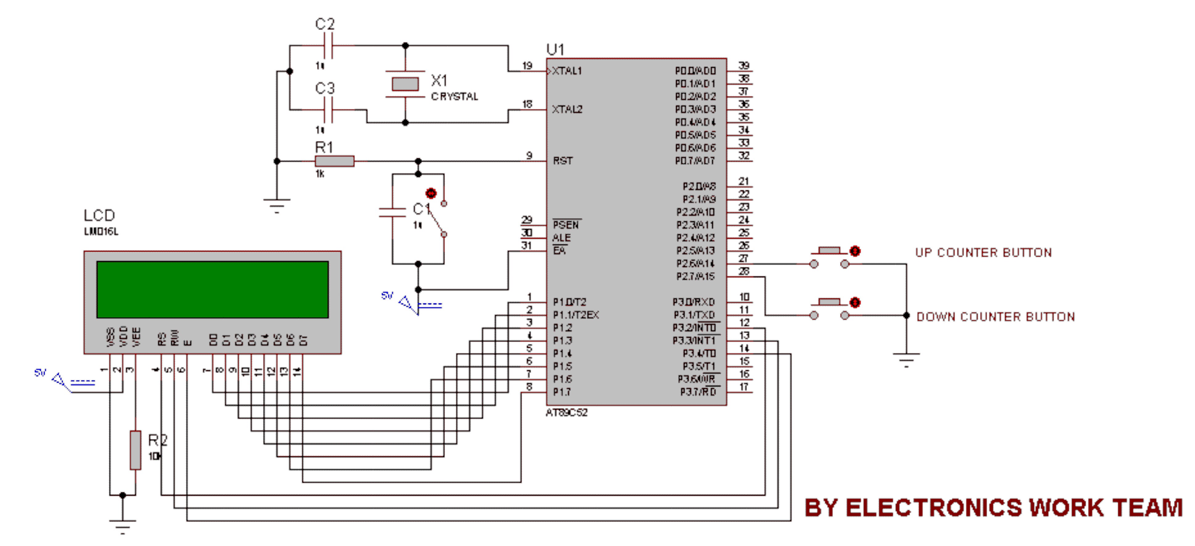
This circuit utilizes a 16x2 LCD to display a count value using an 8051 microcontroller. The maximum count value is set to 99. The circuit consists of the 8051 microcontroller, a 16x2 LCD, and two switches designated for incrementing...
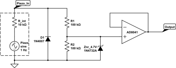
The intention is to utilize the sensor as a force sensor. It has been observed that the voltage output increases with the amount of pressure applied, although this output is only sustained for a brief period. This behavior is...