
Guitar Overdrive circuits
Another common use for these pedals is as a middle booster to drive a valve amplifier harder. This is done by setting little or no drive, but with the level set high.
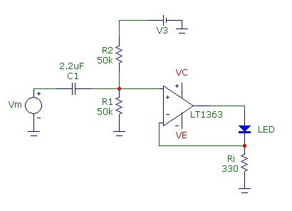
In the schematic, you can see two silicon diodes, back to back, in the negative feedback path of an op-amp. This arrangement gives symmetrical soft-clipping. These were originally sold without the tone control. The design is nearly identical to the Ibanez Tube Screamer with 2 important changes. More boost is available, but is partly offset by using 2 diodes in one direction and only one in the other. This produces asymmetrical soft clipping, meaning that one side of the waveform is clipped more severely than the other. A more common implementation of asymmetrical clipping is to use 2 silicon diodes, with a germanium diode in series with one of them.
There is lively debate on the Internet about whether this sounds more natural, and whether it better emulates some asymmetric valve phase splitter designs. In any case, it does add a little character, and therefore suits humbucker guitars well.
Marshall Pedals: Blues Breaker, Drive Master & Shred Master These three pedals were released in the early 90's, and use different clipping and tone shaping techniques to deliver different sounds.
The Blues Breaker uses silicon diodes in series with a resistor, in the op-amp feedback path for very soft clipping. It's therefore a very subtle pedal, with warm sounds at low to medium overdrive, but can sound a little fuzzy at high gain. Retention of guitar timbre and dynamics is good, and intermodulation is acceptable.
The Drive Master uses LEDs shunting to ground for symmetrical soft clipping. This pedal is noted for its howling Marshall stack-like qualities with single note solos and power chords. Dynamics are good at high drive levels, retention of timbre is excellent, but intermodulation is a problem for anything but simple chord work.
The Shred Master uses silicon diodes shunting the signal to ground, for symmetrical hard clipping. It features bass and treble controls, and a contour control offering middle boost and cut sounds, providing a wide range of usable sounds. Retention of dynamics is good, intermodulation is acceptable, and retention of timbre is good at low drive settings.
Here's a circuit that combines many desirable features. Feel free to experiment with the component values. For example, using lower value capacitors around the tone control will give a brighter sound, and vice versa. The capacitor on the left sets the tone at fully clockwise, while the one on the right sets the minimum tone sound.
This circuit has been updated for 2002. A buffer mode switch has been added. The circuit features:
Battery power is connected by inserting a mono guitar plug into the input socket. This power supply uses a voltage divider to provide half-supply voltage bias to the circuit. Input over-voltage protection (the 1K resistor and 2 x rectifier diodes) is included. A high impedance unity-gain buffer (the BC549 transistor) interfaces the high output impedance of a guitar with the following circuitry. A high pass filter (the 2.2K resistor and 0.15uF capacitor) compensates for the natural low-middle emphasis of guitar pickups. A soft-clipping non-linear amplifier (the 1st half of the TL072 and the 4 diodes in the feedback path) includes variable gain control. A switch allows for soft-clipping (overdrive) or hard clipping (distortion, with the 2 diodes to ground). A low pass filter compensates for the high harmonics added in the clipping stages (the 6.8nF capacitor). The tone control is a variable low pass filter (50K pot and a second capacitor) to customize the amount of treble cut. An output buffer with 6dB of gain provides a low impedance output. A level control allows the pedal to boost or match normal guitar levels or serve as a middle booster with low gain and high level settings. A footswitch is included to use or bypass the circuit. When bypassed, the overdrive effect is shorted, preventing background "fizz" from bleeding into the clean signal. An LED indicates when the effect is on, using a Zener diode to restrict available voltage to the LED to give early indication of battery failure. A bypass mode switch allows for hard bypass to preserve the original tone (and for bypass to work even if the battery is dead), or buffer mode to drive long leads without treble loss or to drive other effects such as volume pedals without tone loss.
The op-amp should be any dual low noise device, such as a TL072. The 1N4148 diodes can be any small signal silicon diodes. The 1N4004 diodes can be any 1 amp rectifier diodes (e.g., 1N4007 is acceptable). The input buffer transistor should be any high gain low noise device, such as a BC549.
The top left portion of this circuit supplies 9V power and 4.5V bias to the rest of the circuit. All 9V points should be connected together, and all 4.5V points should be connected together.Although labelled as distortion, this is a soft clipping device, using germanium diodes. It's a good example of how little you need for a good basic sound. You could easily swap (or switch) these diodes to silicon types for hard clipping. Not necessarily the next pedal chronologically, but look at how similar this design is. It uses 2 silicon diodes for symmetrical hard clipping. I would also expect that at high gain settings, the IC also clips to the supply rails. No discussion on overdrive pedals is complete without looking at the Ibanez Tube Screamer. There have been several minor variations of the pedal released by Ibanez, and a larger number of variations sold by boutique pedal manufacturers. Nevertheless, the green Ibanez box is a very smooth sounding pedal that retains the guitar timbre well, and for that reason works well with single coil guitars. There is not an enormous amount of drive available, and the tone control is subtle. Like many overdrive pedals, there is some middle boost, caused by the bass cut before overdrive, and treble cut afterwards.
Another common use for these pedals is as a middle booster to drive a valve amplifier harder. This is done by setting little or no drive, but with the level set high. In the schematic, you can see two silicon diodes, back to back, in the negative feedback path of an op-amp. This arrangement gives symmetrical soft-clipping. These were originally sold without the tone control. The design is nearly identical to the Ibanez Tube Screamer with 2 important changes. More boost is available, but is partly offset by using 2 diodes in one direction and only one in the other.
This produces asymmetrical soft clipping, meaning that one side of the waveform is clipped more severely than the other. A more common implementation of asymmetrical clipping is to use 2 silicon diodes, with a germanium diode in series with one of them.
There is lively debate on the Internet about whether this sounds more natural, and whether it better emulates some asymmetric valve phase splitter designs. In any case, I think it does add a little character, and therefore suits humbucker guitars well. Marshall Pedals: Blues Breaker, Drive Master & Shred Master These three pedals were released in the early 90's, and use different clipping and tone shaping techniques to deliver different sounds.
The Blues Breaker uses silicon diodes in series with a resistor, in the op-amp feedback path for very soft clipping. It's therefore a very subtle pedal, with warm sounds at low to medium overdrive, but can sound a little fuzzy at high gain.
Retention of guitar timbre and dynamics is good, and intermodulation (read above) is acceptable. The Drive Master uses LEDs shunting to ground for symmetrical soft clipping. I like this pedal for its howling Marshall stack-like qualities with single note solos and power chords. Dynamics are good at high drive levels, retention of timbre is excellent, but intermodulation is a problem for anything but simple chord work.
The Shred Master is not quite the animal its name implies. It uses silicon diodes shunting the signal to ground, for symmetrical hard clipping. Bass and treble controls, and a contour control offering middle boost and cut sounds give a wide range of usable sounds, although I'm not convinced shred is one of them. Retention of dynamics is good, intermodulation is OK, and retention of timbre is good at low drive settings.
Do It Yourself! top Here's a circuit that combines many desirable features. Feel free to experiment with the component values. For example, using lower value capacitors around the tone control will give a brighter sound, and vice versa. The capacitor on the left sets the tone at fully clockwise, while the one on the right sets the minimum tone sound.
This circuit has been updated for 2002. A buffer mode switch has been added - see the notes below (normally you would just wire this permanently the way you want to use it. Also, thanks to Todd Modjeski who pointed a correction required for the input over-voltage protection.
The circuit features are: Battery power is connected by inserting a mono guitar plug into the input socket This power supply uses a voltage divider to provide half-supply voltage bias to the circuit Input over-voltage protection (the 1K resistor and 2 x rectifier diodes) High impedance unity-gain buffer (the BC549 transistor) to interface the high output impedance of a guitar with the following circuitry High pass filter (the 2.2K resistor and 0.15uF capacitor) to compensate for the natural low-middle emphasis of guitar pickups Soft-clipping non-linear amplifier (the 1st half of the TL072 and the 4 diodes in the feedback path) with variable gain control A switch to use soft-clipping (overdrive), or apply hard clipping (distortion, with the 2 diodes to ground) Low pass filter to compensate for the high harmonics added in the clipping stages (the 6.8nF capacitor) The Tone control is a variable low pass filter (50K pot and a second capacitor) to allow you to customise the amount of treble cut An output buffer with 6dB of gain to provide a low impedance output A Level control to allow you to use the pedal to boost or match normal guitar levels (or use as a middle booster with low gain and high level settings) A footswitch to use or bypass the circuit When bypassed, the overdrive effect is shorted, so no background "fizz" bleeds into the clean signal LED indication to show when the effect is on, used with a Zener diode to restrict available voltage to the LED to give early indication of battery failure Bypass mode switch - use hard bypass to preserve original tone (and for bypass to work even if the battery is dead), or use buffer mode to drive long leads without treble loss, or to drive other effects such as volume pedals without tone loss Notes The Op Amp should be any dual low noise device, such as a TL072. The 1N4148 diodes can be any small signal silicon diodes. The 1N4004 diodes can be any 1 amp rectifier diodes (eg 1N4007 is OK also). The input buffer transistor should be any high gain low noise device, such as a BC549. The top left portion of this circuit supplies 9V power and 4.5V bias to the rest of the circuit. Connect all the 9V points together, and connect all the 4.5V points together. 🔗 External reference
Related Circuits
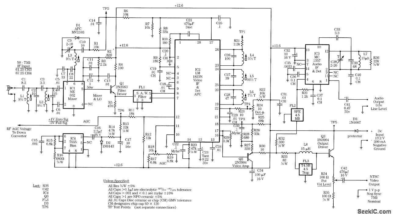
Radio-frequency schematics (also see NE602 datasheet and application note). This page contains electronic circuits related to RF receivers. This index features a broad collection of RF receiver circuits. Radio-frequency (RF) schematics are essential for designing and implementing circuits that operate...
The AM transmitter circuit consists of an audio amplifier and an RF oscillator. The oscillator is constructed around transistor Q1 and its associated components. The tank circuit, which includes inductor L1 and variable capacitor VC1, is tunable from approximately...
Common Light Emitting Diodes (LEDs) require a direct current (DC) forward bias of 10 to 20 mA for optimal performance. The maximum allowable DC current typically ranges from 30 to 50 mA. The emitted light color, or wavelength, from...
The two circuits below illustrate opening a relay contact a short time after the ignition or light switch is turned off. The capacitor is charged and the relay is closed when the voltage at the diode anode rises to...
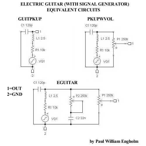
A simple electric guitar SPICE subcircuit has been designed, which features a signal generator producing a 440 Hz sine wave output at 100 mV. This electric guitar SPICE subcircuit serves as a fundamental tool for simulating the behavior of an...
The DD-2 is a highly regarded digital delay pedal that emulates an analog sound. It was initially sold from 1983 until it was discontinued in 1986, after which it was relaunched without any modifications as the DD-3 (noting that...