
Guitar Tremolo Unit
The described circuit is a straightforward modulator oscillator designed for audio applications. The core of the circuit utilizes a dual operational amplifier (op-amp), specifically the LM1458, which is sufficient for the requirements as it does not necessitate ultra-low noise characteristics. The op-amp operates in a feedback configuration to generate a triangle wave output. This waveform is produced through the charging and discharging cycles of capacitor C3, which is integral for shaping the oscillator's output.
The circuit employs low-noise NPN transistors as buffers, which serve to isolate the op-amp from the load, ensuring that the input impedance remains high while maintaining a low output impedance. This buffering is essential for preserving signal integrity and minimizing distortion when interfacing with subsequent circuit stages.
In scenarios where the modulator is integrated into an existing amplifier, the input transistor may be omitted if the amplifier provides a low-impedance drive. This can streamline the design and reduce component count. Similarly, the second transistor can be bypassed if a high-impedance input is available, although this is less common since modulators are typically placed before tone control circuits, which might not provide the necessary high-impedance input.
The output from the oscillator is then used to drive an LED within an opto-coupler, facilitating isolation between different circuit sections while allowing for signal modulation. In cases where the recommended opto-coupler (Vactrol) is unavailable, a high-quality alternative should be sourced to ensure performance consistency.
Overall, this circuit exemplifies a modular approach to audio signal processing, allowing for flexibility in component selection and integration into broader audio systems while maintaining essential functionality.The unit is simple to build, and does not need really low noise opamps, since they only act as a modulator oscillator. I used 1458 dual types in the prototype, and they are more than good enough. The transistors can be any low noise NPN type, and they are simply buffers, ensuring a high input impedance and low output impedance.
If the unit is to built into an amplifier, it may well be possible to leave out the input transistor, since a low impedance drive circuit is probably already available from an existing opamp. It may also be possible to leave out the second transistor if a high impedance input is available at the insertion point.
This is somewhat unlikely, since the most common place to have the modulator is before the tone controls. The oscillator is a simple opamp feedback type, and produces a triangle wave from the capacitor (C3). This is amplified and buffered, and fed to the LED in the opto-coupler. If you are unable to obtain this device (made by Vactrol), use a high quality Lig 🔗 External reference
Related Circuits

This circuit has the advantage of transferring almost all the energy from the collapsing magnetic field of L2 to C2. In contrast, a typical Joule thief circuit allows some of this energy to return to the battery. This efficiency...
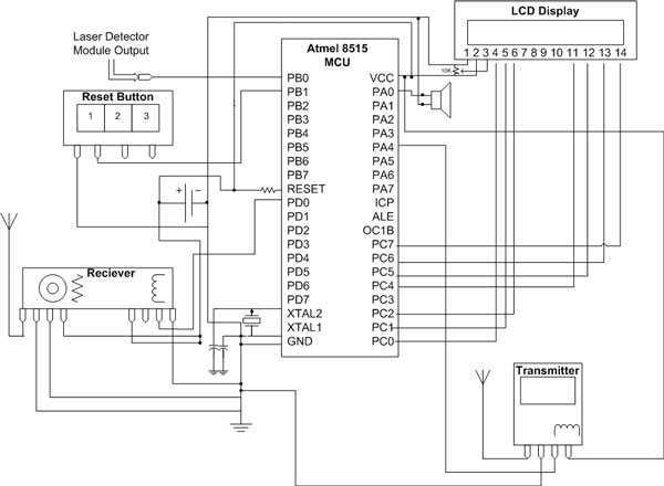
The hardware for this project had three main components: laser gun assembly, detector unit, control pad. The detector unit's function was to simply detect a laser pulse over a small area sent by the laser driver circuit on the...

This preamplifier is designed as a portable unit, ideal for amplifying signals generated by guitar pickups, particularly the "bug" types used with acoustic instruments. It can be utilized with any type of device and pickup. The unit features a...
The following circuit illustrates the circuit diagram of a motor control unit. This circuit is based on the LM317 integrated circuit. Features include diodes that protect the regulator. The motor control unit circuit utilizes the LM317 voltage regulator to provide...
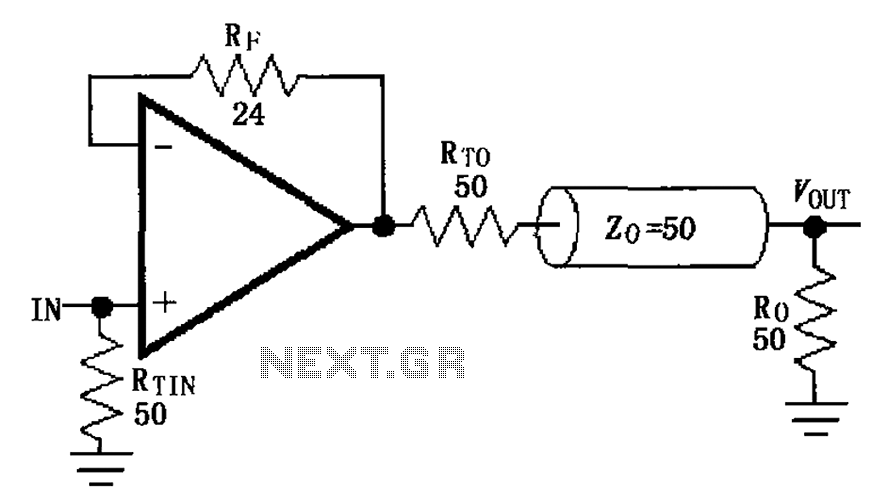
The MAX4450/4451 unity gain line is illustrated in the driving circuit. The MAX4450/4451 features internal compensation, a 24-ohm resistor in series within a feedback loop, along with capacitors and inductors that can reduce the Q value of the feedback...
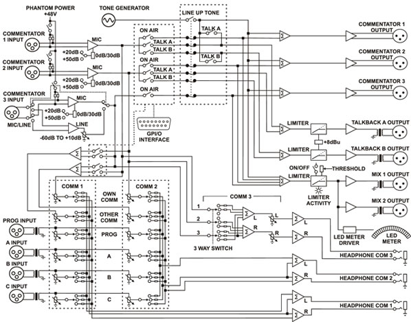
The CM-CU21 is a high-quality, portable Commentator Unit. Its robust construction and versatile features make it suitable for use in a wide range of environments. It offers two fully equipped commentator positions and a third guest position that can...