
H-Bridge (A2060H) Manual
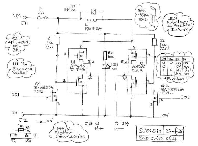
The A2060C uses the LC4256V-10T100I programmable logic chip from Lattice Semiconductor. The circuit diagram for the H-Bridge extension to the A2060 circuit is A2060H_3. You will find the latest version of the P2060H logic code here. For an example of an application of the A2060H, see the Long Guide Tube. The A2060H is a LWDAQ device. It obtains power for its internal logic from the LWDAQ, but motor power must be delivered by a separate positive power supply, which we connect to the VCC (J11) and 0V (J12) terminal. The motor plugs into the M+ (J13) and M ’ (J14) terminals. The sixteen LEDs along the top of the board show the command bits. Table 1: Command Bit Allocation of the A2060H. An "X" means the command bit serves no function. The SPD6. SPD0 bits set the rotation speed. The DIR bit sets the direction. In Versions 1-7 of the firmware, the speed and direction bits occupied DC1-DC8. We moved them in Version 8 so that they would not interfere with the WAKE and LB bits. You can transmit a command to the A2060H using the Transmit button of the Diagnostic Instrument. Enter the command in hexadecimal format in the transmit entry box, make the A2060H the target of the Diagnostic Instrument and press Transmit.
Command $FF00 sends the motor in one direction at full speed, and $C000 sends it in the same direction at half-speed. The motor will stop after a couple of seconds unless you send it another movement command before it stops.
You can renew your chosen command automatically with the Diagnostic Instrument by entering transmit in the daq_actions parameter and pressing Loop (the upper one, not the lower one). Each time the instrument acquires new data, it re-sends the movement command. In some cases, such as the rotation motor of the Long Guide Tube, we want to prevent a LWDAQ command from moving the motor at full speed under any circumstances.
Firmware version 10 and higher (P2060H10 and higher) provide a max_speed parameter. We find that with this parameter set to 20, compile the code to its jedec file and re-program the logic to put the limit at roughly 12% of the maximum. The switches will still give full-speed drive, but not random commands. The M+ and M ’ terminals connect to a DC servo motor. Each can either be set at VCC or 0V. The circuit is designed to operate with VCC between 5 V and 24 V. The motor runs when the two terminals are at different levels. The A2060H firmware allows either M+ to be connected to VCC while M ’ is connected to 0V, or M ’ to be connected to VCC while M+ is connected to 0V.
Thus the motor may be driven in both directions, but it cannot be left open circuit. As soon as we connect both terminals to 0V, the motor will stop quickly. Its kinetic energy will generate an electromotive force, which will drive current through the H-Bridge circuit. The current will flow through diodes in the power mosfets, U1 and U2. At such times, or when the motor is belabored by torque to the point of stalling, fuse F1 is likely to blow.
We replaced F1 with a wire link in some versions of the A2060H. The H-Bridge varies the speed of the motor by switching VCC onto one terminal for a fraction of the time, while holding the other terminal at 0V. The switching period is 400 s. At half-speed, the motor is connected to VCC for 200 s and 0V for the remaining 200 s. This creates a 2. 5-kHz whine in the motor coils, which young people can hear better than old people. Each time the H-Bridge turns off VCC to the motor, a certain amount of energy is dissipated in the power mosfets U1 and U2.
This energy heats up the mosfets whether there is a motor connected or not. At a switching frequency of 10 kHz, the mosfets get so hot after a while that they melt their plastic sockets. At 2. 5 kHz, they are warm, but they never get hot. The DIR bit sets the terminal of the motor to which VCC will be connected. This determines the direction of rotation. The bits SPD6. SPD0 set the length of the VCC portion of the switching period, and thus determine the speed. If they are all set, the pulse is at its maximum length and voltage is the entire time. The motor runs at full speed. If the bits are all zero, the motor stops. The two sides of the H-Bridge are identical. The first side consists of Q1 and U1. The Q1 transistor in combination with resistor R1 turns a 3. 3-V logic signal into a switching voltage suitable for turning on and off the complimentary power mosfets of U1, AOP605.
When Q1 is on, the gates of the two power mosfets are brought down to 0V, so the top one is on and the bottom one is off. The M+ terminal is connected to +24V. When Q1 is off, M+ is connected to 0V. During the transition, both transistors will be on at the same time, and this is when the H-Bridge generates its own heat.
When Q1 turns on, which is when we connect VCC to M+, the transition takes place in less than 1 s and the heating is negligible. But when Q1 turns off, it is resistor R1 that pulls up the gates of the mosfets, and it does this with a time constant of a few microseconds.
During these few microseconds, the power mosfets are both conducting. The current drawn from VCC is, however, limited by inductor L1. With 24V across it, the current in L1 builds up at 2. 4 A/ s. As the current starts to increase through the conducting mosfets, L1 drops the voltage on the source of the p-channel mosfet (the upper of the two), which in turn decreases its gate-source voltage, and so tends to turn it off. Thus L1 limits the currrent in two ways, making it possible for us to switch the H-Bridge using Q1, Q2, R1, and R2, instead of a more complicated arrangement of push-pull transistors that would complete both transitions in negligible time.
The turn-off of Q1 ends up taking 8 s, during which time the average current drawn from a 24-V VCC is around 1 A. At a switching frequency of 2. 5 kHz, U1 dissipates 0. 5 W, which raises its temperature by 40 °C. At 10 kHz, the package heats up by 160 °C, at which point it starts to suffer internal damage and to melt its plastic socket.
The 4-A fuse is essential for protecting the mosfets against current surges through the motor. Resistor R3 and lamp LED1 indicate when the motor power is connected and the 4-A fuse is intact. This fuse will blow frequently if the A2060H is not equipped with R12 between pins 1 and 5 of J1. This 1K0 resistor pulls up the T+ line to +5V when T+/T ’ are high-impedance at the LWDAQ multiplexer or LWDAQ driver. If we are running the motor while simultaneously measuring position or load with another LWDAQ device, T+/T ’ will be high-impedance when these other measurements are taking place.
Without R12, motor-current induced noise will produce spikes on T+/T ’, thus generating spurious commands that stop the motor so suddenly the fuse blows. With R12, however, we observe no fuse blowing, unless we deliberately instruct the motor to go from full-speed in one direction to full speed in the other.
Therefore, our software always stops the motor before reversing its direction. 🔗 External reference
Related Circuits
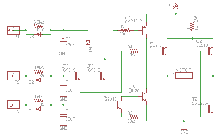
An old RC car is available, but it lacks the transmitter. A custom receiver/transmitter has been built using a microcontroller and a 2.4 GHz transceiver. However, there is uncertainty regarding the functionality of the car's original H-Bridge circuit. The H-Bridge...

This manual is intended for use by authorized Sinclair dealers, engineers, and representatives as a guide for rectifying faults in the Sinclair ZX Printer. Repair and renewal procedures are limited to those specific to this printer; standard procedures for...
It was previously assumed that dynamic braking would be most effective at higher speeds. However, tests conducted with a Faulhaber (Micro Mo) gear motor demonstrated that the brake could hold the motor almost stationary. These gear motors are constructed...
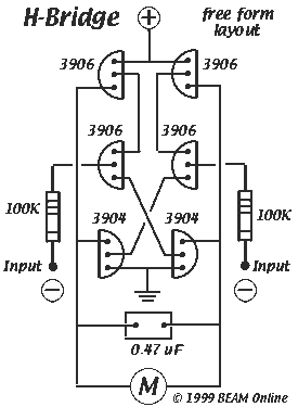
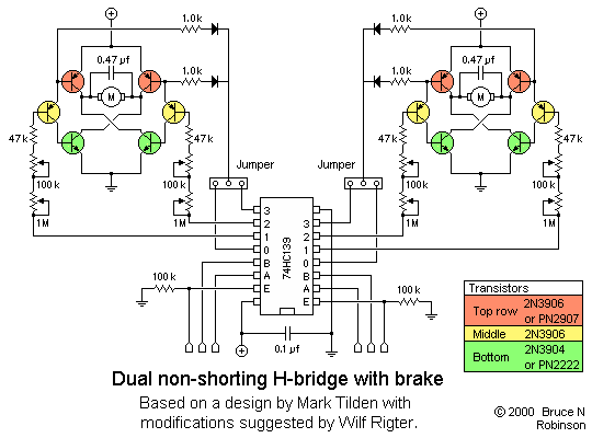
Mark Tilden's 6-transistor H-bridge Design, limitations, usage This is the six transistor "Tilden style" H-bridge; while not as old as the original "basic H-bridge," this goes "way back," and is the basis for many BEAM driver circuits. * Up to 800...
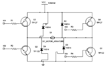
The diagram below illustrates an H-Bridge circuit featuring four inputs and an external power supply. The control application must enable the motor to operate in both forward and reverse directions. The H-Bridge is a crucial component in motor control applications,...
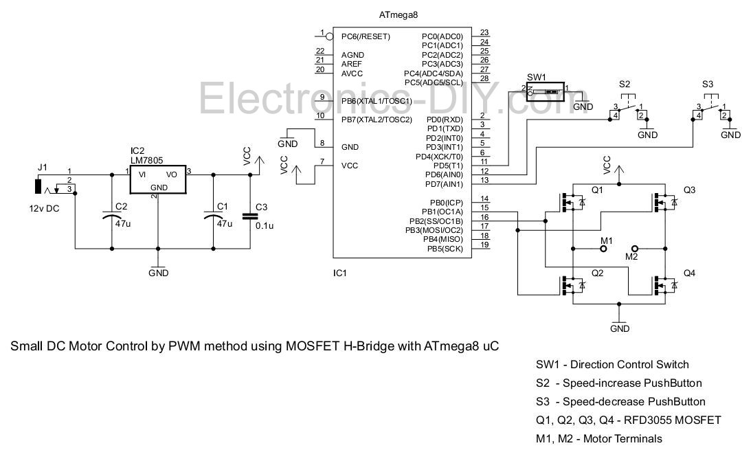
This project involves controlling a small DC motor, sourced from an old personal cassette player, using the ATmega8 microcontroller. The ATmega8 features three PWM channels, of which two are utilized in this application. The PWM signals are sent to...
Warning: include(partials/cookie-banner.php): Failed to open stream: Permission denied in /var/www/html/nextgr/view-circuit.php on line 713
Warning: include(): Failed opening 'partials/cookie-banner.php' for inclusion (include_path='.:/usr/share/php') in /var/www/html/nextgr/view-circuit.php on line 713