
h bridge
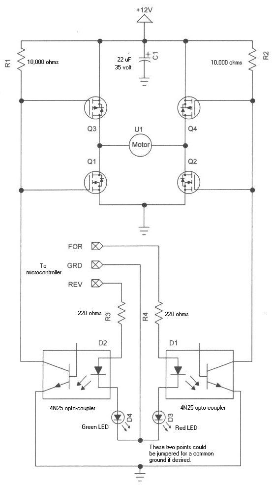
The H-bridge motor control circuit is an essential configuration for driving DC motors in both forward and reverse directions. It utilizes four power MOSFETs arranged in a bridge configuration, allowing for bidirectional control of the motor.
In this setup, two pairs of MOSFETs are used: one pair for controlling the current flow in one direction and the other pair for the opposite direction. The gates of the MOSFETs are driven by a microcontroller or a PWM signal, enabling precise control over the motor speed and direction.
The operation of the H-bridge can be summarized as follows: when the upper left and lower right MOSFETs are turned on, the current flows through the motor in one direction, causing it to rotate clockwise. Conversely, when the upper right and lower left MOSFETs are activated, the current reverses, and the motor rotates counterclockwise.
To prevent short circuits and ensure safe operation, it is crucial to implement dead time between switching the MOSFETs. This dead time allows one MOSFET to turn off completely before the opposite pair is activated. Additionally, flyback diodes are often included in the circuit to protect the MOSFETs from back EMF generated when the motor is de-energized.
The selection of appropriate MOSFETs is vital, as they must handle the motor's current and voltage ratings. Proper heat dissipation methods, such as heat sinks or active cooling, should also be considered to maintain the reliability of the circuit during operation.
Overall, the H-bridge motor control circuit not only provides a practical application for power MOSFETs but also serves as a foundational learning tool for understanding motor control techniques in electronic design.Learning how to use power MOSFETs by building an H-bridge motor control.. 🔗 External reference
Related Circuits
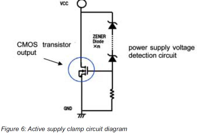
This article presents a high reliability 1200V High Voltage Integrated Circuit (1200V HVIC) for half bridge driver applications, aimed at reducing the IC's supply current by approximately 50%. The 1200V High Voltage Integrated Circuit (HVIC) is designed specifically for half-bridge...
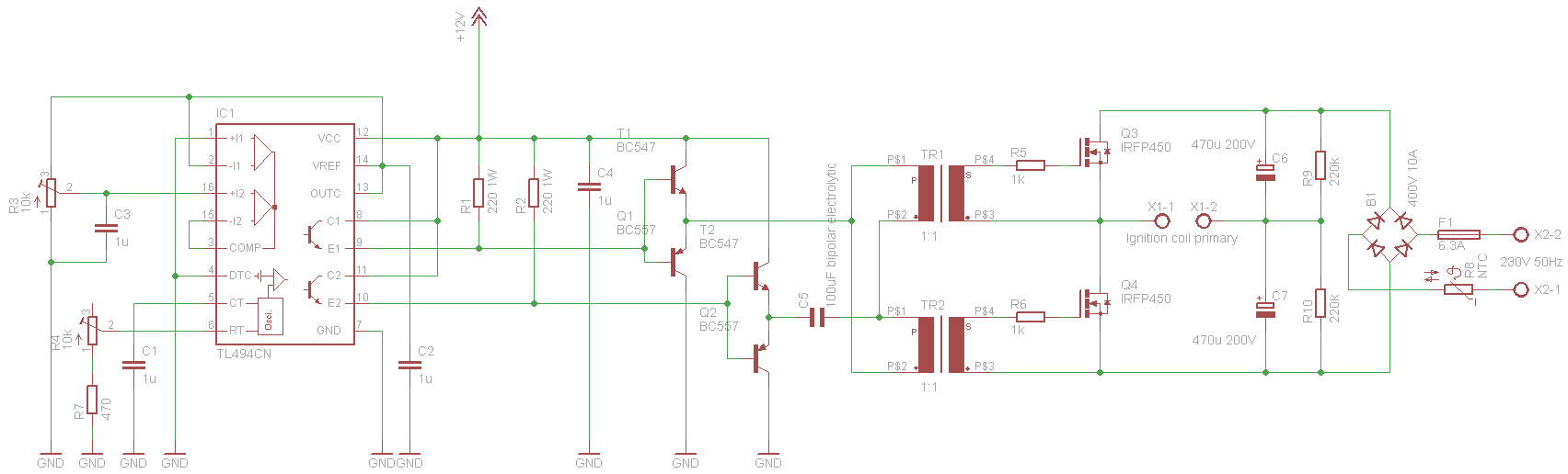
Ignition coil drivers that utilize an oscillator chip like the NE555 and a single switching device are a common beginner high voltage project. This version highlights some of the most important issues associated with this approach. Firstly, a desire...
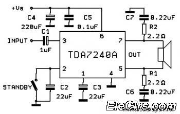
The following circuit diagram is a bridge amplifier specifically designed for car audio systems. The circuit is very simple, utilizing a few external components to support the power IC TDA7240A. This circuit will produce a maximum power output of... The...
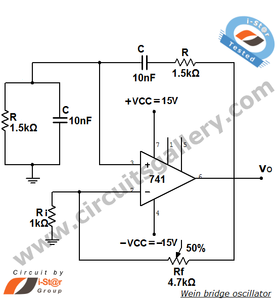
The Wien bridge oscillator is a high-stability audio frequency sine wave oscillator known for its simplicity. An oscillator is defined as a circuit that generates periodic electric signals, such as sine waves or square waves. Applications of oscillators include...
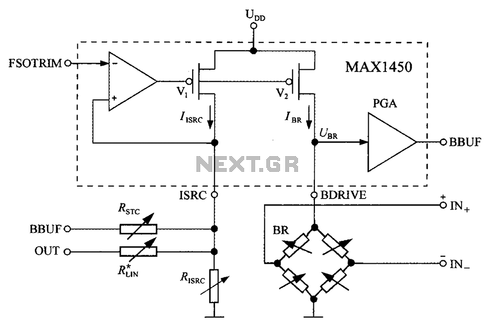
The circuit diagram for the bridge integrated pressure signal conditioner MAX1450 is composed of various components. The MAX1450 is a high-performance integrated circuit designed for signal conditioning in pressure sensing applications. It is particularly suited for use with resistive bridge...
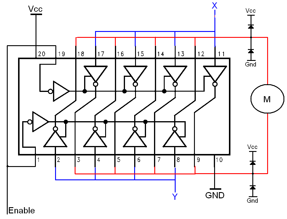
The H-bridge is a well-known and widely used circuit configuration for driving brushed DC motors. It enables straightforward control of motor direction, allowing for both forward and reverse operation. The H-bridge circuit consists of four switches, typically implemented using transistors...