
Simple H-bridges Tutorial

The H-bridge circuit consists of four switches, typically implemented using transistors or MOSFETs, arranged in a bridge configuration. The arrangement of these switches allows for the application of voltage across the motor terminals in either direction. By turning on specific switches, the current can be directed through the motor in one direction for forward motion, or in the opposite direction for reverse motion.
In its simplest form, the H-bridge can be controlled using two input signals. For example, when one input is high and the other is low, the motor will rotate in one direction. Conversely, if the inputs are reversed, the motor will rotate in the opposite direction. Additionally, if both inputs are low, the motor will stop, and if both inputs are high, it may lead to a short circuit condition, which should be avoided.
The H-bridge can also incorporate features such as pulse-width modulation (PWM) control to vary the speed of the motor. By adjusting the duty cycle of the PWM signal applied to the switches, the average voltage and current supplied to the motor can be controlled, allowing for precise speed regulation.
Protection mechanisms, such as diodes, are often included in the design to prevent back EMF generated by the motor from damaging the circuit components. These diodes, known as flyback diodes, provide a path for the inductive kickback when the motor is turned off, ensuring the longevity and reliability of the H-bridge circuit.
Overall, the H-bridge is an essential component in motor control applications, providing efficient and effective means to manage the operation of DC motors in various electronic systems.The H-bridge: The H-bridge is a commonly known, and commonly used way to drive a brushed DC motor. It allows for simple forward/reverse drive, .. 🔗 External reference
Related Circuits
Normally, an analog-to-digital converter (ADC) requires interfacing through a chip to convert analog signals into digital format. This necessitates both hardware and software, resulting in increased complexity and overall cost. The circuit presented here is configured around the ADC...

A relay is an electromechanical switch that operates by opening and closing under the control of another electric circuit. When current flows through the relay's coil, a magnetic field is generated, causing an armature to move, which either establishes...
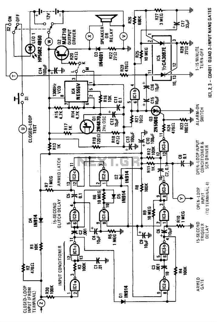
This house alarm circuit features both open and closed loop sensors and includes a self-shutdown function. The delay after triggering can be adjusted between 1 minute and 12 minutes, while the delay before triggering is set at 13 seconds....
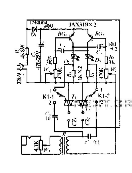
A 220V mains power supply is reduced using a control circuit designed by N. Guanidine D. Yi. The circuit features a spike Bode and provides a +9V voltage supply. It includes components such as a control port (G), a...
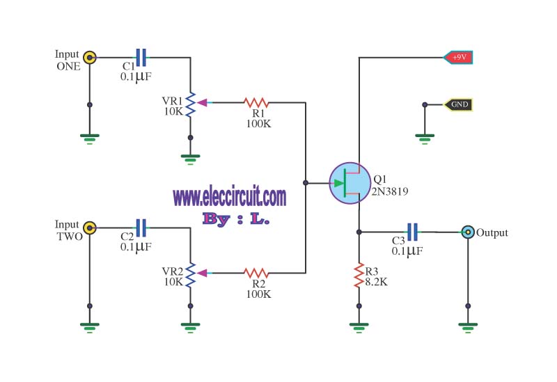
This circuit is a simple mixer circuit that can mix two signal channels into one output channel. It utilizes a codec circuit to convert stereo audio into mono audio. The circuit can also increase the number of channels by...
This is a simple square wave generator circuit constructed using the IC 74LS00, capable of producing square wave signals with frequencies ranging from 20 Hz to 1 MHz. The circuit exhibits sufficient stability for most applications. The output frequency...