
h bridge using mosfet transistor pwm

The H-Bridge circuit is designed to control a DC brushed motor by allowing bidirectional operation through the use of pulse-width modulation (PWM) for speed control. The configuration consists of two pairs of transistors, where each pair is responsible for switching the motor's connection to the power supply in opposite polarities.
In this setup, the inputs A and B are connected to the bases of the 2N3904 transistors, which act as signal amplifiers to drive the gates of the MOSFETs. The IRF7317 MOSFETs are used in the H-Bridge configuration to handle the high current and voltage required by the motor. The MOSFET IRF7905 is specifically designated for PWM control, allowing for efficient speed modulation of the motor.
The operation of the H-Bridge can be summarized as follows: when input A is high and input B is low, the motor will spin in one direction (e.g., clockwise). Conversely, when input A is low and input B is high, the motor will spin in the opposite direction (e.g., counterclockwise). The PWM signal, applied to the gate of the IRF7905 MOSFET, modulates the effective voltage supplied to the motor, thereby controlling its speed. The frequency of the PWM signal is set at 1kHz, which is suitable for many DC motors, providing a smooth operation without audible noise.
Protection diodes should be added across the MOSFETs to prevent back EMF generated by the motor from damaging the transistors and MOSFETs during switching. It is crucial to ensure that the selected components can handle the maximum current draw of 1.1A at the operating voltage of 6V. Proper heat dissipation techniques should also be considered for the MOSFETs to prevent thermal overload during operation.
This H-Bridge configuration is a versatile solution for controlling DC brushed motors in various applications, allowing for precise speed and direction control through simple input signals.Make H-Bridge for controlling DC brushed motor with PWM. One bridge will control 1 DC motor. Bridge will have 3 inputs: A, B and PWM. A and B will be direction control while one PWM signal will control motor speed no matter in which direction it will spin. Will this circuit work (of course ill have to add protection diodes but first i want to know if it will work with PWM) A and
B will select direction of motor and no matter if it will spin clockwise or counterclockwise same one PWM signal will set its speed. Transistors connected to A and B are 2n3904, P and N mosfets of bridge will be IRF7317 and mosfet with PWM will be IRF7905.
Motor voltage is 6V and maximum current draw is 1. 1A. PWM freq 1kHz 🔗 External reference
Related Circuits
More: The provided input lacks specific details or context regarding an electronic circuit or schematic. To create a comprehensive electronic schematic description, it is essential to include key components, their interconnections, and the overall functionality of the...
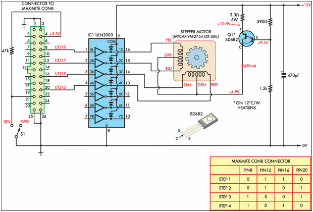
Designing and implementing this circuit was an exciting endeavor. The design of the interface involved learning how to control a device from a computer. A parallel port cable was utilized for this purpose, enabling instant control of the stepper...
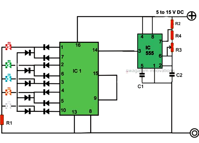
An LED light chaser circuit is an electronic configuration designed to illuminate a group of LEDs in a predetermined sequence. A commonly used integrated circuit (IC) for creating this type of LED sequencer circuit is the 4017. This IC...
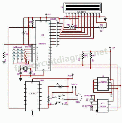
The circuit is a bell timer. This project utilizes the AT89S52 microcontroller and an I2C EEPROM for storing alarm timings. Additionally, the 7-segment display has been replaced with an LCD display. The DS1307 is employed for real-time clock functionality....

This project demonstrates how a car can be controlled remotely from anywhere in the world by accessing its diagnostic systems and onboard web server. The goal is to keep the car continuously connected to the Internet 24/7, even when...
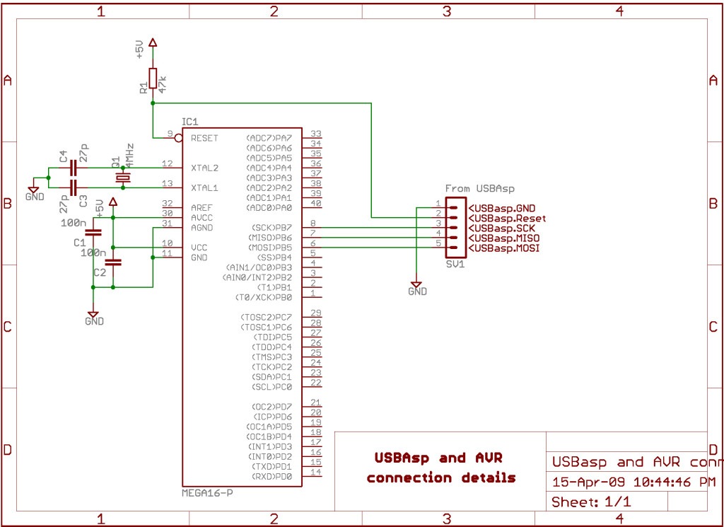
AVRDude is a program designed for burning hex code into microcontrollers. USBasp is a USB-based programmer for AVR microcontrollers. This tutorial will demonstrate how to use AVRdude to burn hex files into an AVR microcontroller using USBasp. The AVRdude...