
Halogen Lamp Dimmer With Soft Start

Dimmers that employ pulse width modulation (PWM) function by rapidly turning the power supplied to the lamp on and off at a frequency that is imperceptible to the human eye. The ratio of the on-time to the off-time, known as the duty cycle, determines the average power delivered to the lamp, thus controlling its brightness. A higher duty cycle results in a brighter light, while a lower duty cycle dims the light.
In a typical PWM dimmer circuit, a microcontroller or a dedicated PWM controller generates the switching signal. This signal is then used to drive a power transistor or MOSFET, which acts as a switch for the load (the lamp). The circuit may also include additional components such as capacitors for filtering and protection diodes to prevent back EMF from inductive loads.
Furthermore, dimmers that come with a switch faceplate often incorporate user-friendly features, such as tactile feedback or visual indicators, to enhance the user experience. These faceplates may also house additional circuitry to facilitate features like remote control operation or integration with smart home systems, allowing for more advanced control over lighting environments.
In summary, PWM dimmers represent an efficient means of controlling light intensity, providing flexibility and energy savings while maintaining a simple user interface. The implementation of such dimming technology can vary, but the fundamental principles of PWM remain consistent across different designs.Most dimmers use pulse width modulation (PWM) to control the amount of power that is delivered to the lamp. Those that come bundled with a switch faceplat.. 🔗 External reference
Related Circuits

The circuit is designed to stabilize the brightness of lamp L using a thyristor-based AC automatic voltage regulator. The thyristor T5 is connected diagonally across the bridge circuit. The trigger pulses are generated by components VT1, VT2, and VT3,...

This circuit for a powerful flashing lamp is suitable for use in vehicles. The LM395 integrated circuit, also known as a super-transistor, is a highly robust monolithic power transistor that includes features such as thermal protection and current limiting....

The following circuit illustrates a Bedside Lamp Timer Circuit Diagram. This circuit is based on the CD4060 integrated circuit. Features: An LED illuminates for approximately 25 seconds. The Bedside Lamp Timer Circuit utilizes the CD4060 IC, which is a versatile...
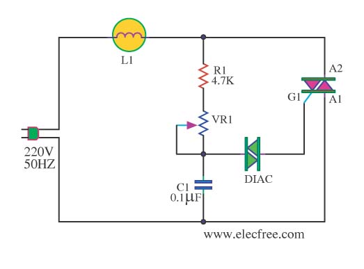
This circuit is designed to dim a light bulb with a maximum power rating of 100W. If the triac experiences high temperatures, it is essential to use a heat sink or allow for adequate heat dissipation. The diac functions...
This circuit operates a LED in pulsing mode, i.e. the LED goes from off state, lights up gradually, then dims gradually, etc. This operation mode is obtained by a triangular wave generator formed by two op-amps contained in a...

The circuit described on this page is designed around Kingbright's 52mm LED cluster module which comprises 50 red LEDs in a waterproof housing with a brightness in excess of 16000mcd. In the original version of this project each LED...