
Halogen Light Switch Circuit
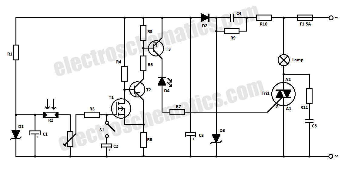
This halogen switch circuit is designed for efficient control of 12V halogen lamps using field-effect transistors (FETs). The FET operates as a switch, regulating the current flow based on the voltage applied to its gate. With a maximum gate voltage of 12V, the circuit is optimized for use with standard 12V halogen lighting systems, making it a practical choice for various applications, including home lighting and automotive uses.
The resistor R1 plays a crucial role in determining the gate voltage. The choice of resistor value—100 kΩ for 6V and 470 kΩ for 12V—allows for flexibility in operation, enabling the circuit to function correctly across different voltage levels. This adaptability ensures that the FET can effectively switch on and off, controlling the lamp's brightness and power consumption.
The circuit can utilize either the BUZ10 or BUZ11 FETs, both of which are capable of handling significant current loads. The BUZ10 can support up to 20A, while the BUZ11 can manage up to 30A, providing ample capacity for most halogen lamps. The choice between these two FETs will depend on the specific current requirements of the application, ensuring reliability and performance.
An important aspect of this circuit is the thermal management of the FETs. The design does not require a heatsink, as the FETs typically reach a maximum temperature of only 17 °C during operation. This characteristic simplifies the design and installation process, reducing the overall size and complexity of the circuit while maintaining safe operating temperatures.
Overall, this halogen switch circuit represents a straightforward yet effective solution for controlling 12V halogen lamps, leveraging the advantages of FET technology to achieve reliable performance and ease of use.In this halogen switch circuit we use a FET transistor because the current is dependent of the FET`s gate voltage. The maximum gate voltage is 12V, so this circuit is adequate for 12 volt lamps. R1 value is 100 k © for 6V and 470 k © for 12V. You can use BUZ10 which can outstand up to 20A or BUZ11 with maximum 30A. You don`t need heatsink for this FETs because they tend to warm up to only 17 °C. 🔗 External reference
Related Circuits
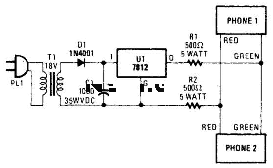
Two telephones can be used as an intercom by utilizing this circuit. Older style rotary phones that are non-electronic may be the most suitable for this application. Additionally, handsets alone can be powered in this manner. This intercom circuit allows...
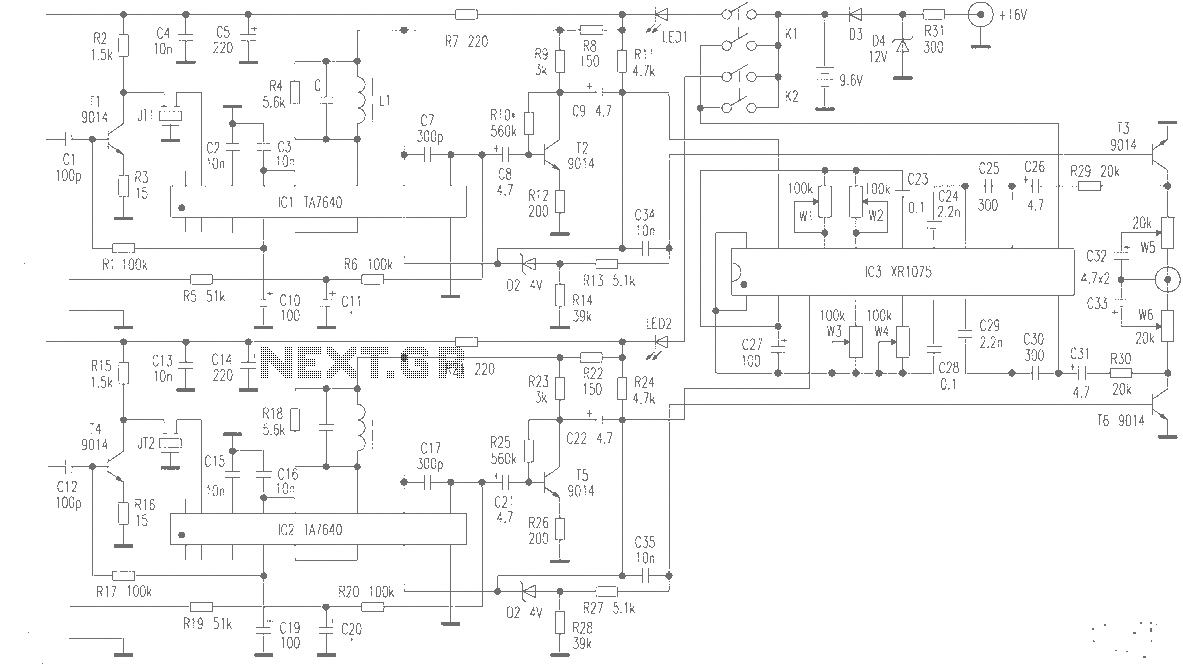
The production of high-quality wireless microphones is a common aspiration among enthusiasts, but achieving a high-performance receiver is challenging. This project explores the use of salvaged FM radio cassette players to enhance an XR1075 audio processor, leading to the...
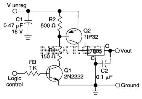
A logic level can control a 7805 regulator with this circuit. Q2 is a series switching transistor controlled by Q1. Q1 is turned on by a logic voltage to its base. This circuit utilizes a 7805 voltage regulator, which is...
This circuit will allow you to connect any tape recorder that has a mic and remote input to a phone line and automatically record both sides of a conversation whenever the phone is in use. You will need to...
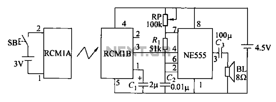
The circuit utilizes an RMIB multivibrator component that operates at a maximum distance. When the distance exceeds a specific threshold, the output pin of the receiver goes low, effectively stopping the oscillation. The NE555 multivibrator, which is part of...
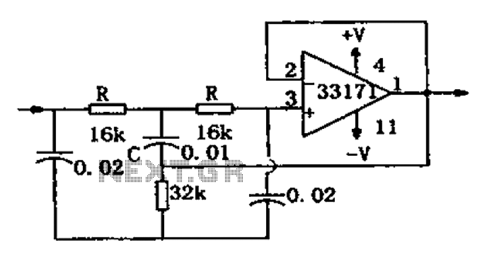
The trap circuit utilizes a high-performance operational amplifier, MC33171, to create the trap. This device features a wide bandwidth and high conversion rate. The component values can be modified by adjusting the capacitance of capacitor C and the resistance...
Warning: include(partials/cookie-banner.php): Failed to open stream: Permission denied in /var/www/html/nextgr/view-circuit.php on line 713
Warning: include(): Failed opening 'partials/cookie-banner.php' for inclusion (include_path='.:/usr/share/php') in /var/www/html/nextgr/view-circuit.php on line 713