
bipolar chopper drive circuit
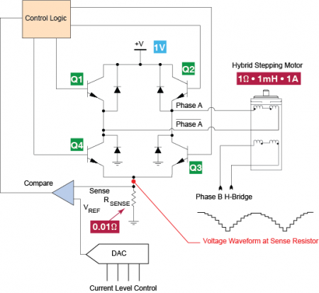
A bipolar chopper drive is an essential circuit configuration used in stepper motor control systems, particularly for achieving precise current regulation. This method employs a bipolar transistor or MOSFET switching arrangement to modulate the voltage applied to the motor windings, enabling efficient and accurate control of the motor's torque and position.
The bipolar chopper drive operates by rapidly switching the power transistors on and off, creating a series of voltage pulses that are applied to the motor coils. This pulse-width modulation (PWM) technique allows for the adjustment of the effective voltage and current flowing through the motor, which directly influences its performance. The chopper drive circuit typically includes a microcontroller or dedicated driver IC that generates the PWM signal based on the desired motor speed and load conditions.
Key components of the bipolar chopper drive include the power transistors, flyback diodes, current sensing resistors, and control circuitry. The transistors are responsible for switching the current, while the flyback diodes protect the circuit from voltage spikes generated when the inductive motor coils are de-energized. Current sensing resistors provide feedback to the control circuit, allowing for real-time adjustments to maintain the desired current levels.
This method is particularly advantageous for stepper motors because it minimizes power loss and heat generation, enabling higher efficiency and better performance over a range of operating conditions. Additionally, the precise control afforded by the bipolar chopper drive allows for smooth motion and improved torque characteristics, making it suitable for applications requiring high levels of accuracy and responsiveness.In today s blog we re going to examine a bipolar chopper drive, a common method for precision current control in stepper motors.. 🔗 External reference
Related Circuits
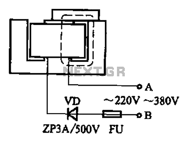
After some minor loss of field magnets, they can be re-magnetized using a homemade method. A scrap of exchanges and contacts, as well as other models like CJ10-60 ~ 15, can be utilized. The circuit operates at 0A (compatible...
The preamplifier described is engineered with a low output impedance, specifically designed to handle long cable runs. This feature allows for listening to a remote music source without the need for expensive screened cables. The preamplifier boasts a very low...
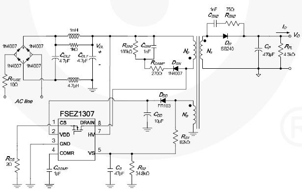
This cell phone charger circuit diagram electronic project is based on the FSEZ1307 third-generation primary side regulation (PSR) PWM controller integrated circuit. The FSEZ1307 cell phone charger can be used for battery charger applications for devices such as cellular...
The cumulative timer circuit comprises resistor R1 and an internal crystal oscillator, represented in a chart. Resistors R1 and R2 are metal film types, while resistors R3 to R5 are rated at 1/8W and also of the metal film...
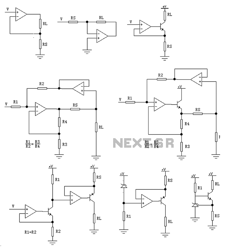
The circuit is designed to provide several constant current outputs to the load resistor RL. The first RL is floating and is rarely utilized. The second RL serves as a virtual ground and is not commonly used either. The...
XP power plug, FU fuse, ST temperature control, T1 low-voltage transformers, S1, S2 door interlock switch, S3 threshold control switch, RT thermal sensor, K1, K2 relay, EL furnace light, M1 wheel motor, M2 fan motor, T2 high-voltage transformer, C...