
LM1893 for Power Line Modem Circuit

The LM1893 power line modem circuit is designed for efficient data communication over existing power lines, capitalizing on the infrastructure already in place. The LM1893 chip serves as the core of the design, facilitating the modulation and demodulation processes required for transmitting and receiving data. The half-duplex communication capability allows for bidirectional data flow, which is essential for applications that require feedback or acknowledgment from the receiving end.
To enhance the performance of the circuit, an impulse noise filter is employed. This filter mitigates the impact of electrical noise that may interfere with the data signals, ensuring a cleaner signal is received. The PLL-based demodulator further improves the reliability of the data transmission by accurately tracking the frequency of the incoming signal, allowing for better synchronization and decoding of the transmitted information.
The transmission process involves the generation of a sinusoidal carrier wave, which is modulated using frequency-shift keying (FSK). This modulation technique allows for the encoding of digital data onto the carrier wave by varying its frequency, making it suitable for transmission over the power line. The rugged on-chip driver of the LM1893 ensures that the modulated signal can be effectively transmitted across the power line, which may have varying impedance and noise characteristics.
The inclusion of a COPS controller and discrete components in the circuit design provides additional flexibility and functionality. The COPS controller can manage various operational parameters, enhancing the overall performance of the modem. Discrete components may include resistors, capacitors, and inductors that are tailored to optimize the circuit's response and reliability.
In summary, the LM1893 power line modem circuit is a sophisticated solution for data communication over power lines, incorporating advanced techniques such as FSK modulation, noise filtering, and PLL demodulation to ensure robust and reliable performance in diverse environments.This design circuit is shows an LM1893 power line modem circuit. This circuit is used to transfer information between remote locations by using the power mains. This circuit uses LM1893 that is used as a power line interface for half-duplex (bi-directional) communication of serial bit stream of virtually any coding. This is the figure of the circu it; To give maximum range, impulse noise filter and a PLL-based demodulator are combined in reception. In transmission, a sinusoidal carrier is impressed and FSK modulated on most any power line via rugged on-chip driver.
Besides LM1893, this circuit also uses a COPS controller and discrete components. [Circuit diagram source: National Semiconductor`s Application Note] 🔗 External reference
Related Circuits
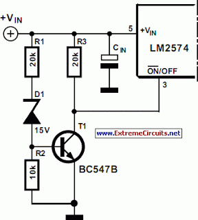
A switching power supply with an output voltage significantly lower than its input voltage exhibits an interesting characteristic: the current drawn by the supply is less than its output current. However, the input power (UI) is greater than the...

The sound produced imitates the rise and fall of an American police siren. When first switched on, the 10 µF capacitor is discharged, and both transistors are off. When the push button switch is pressed, the 10 µF capacitor...
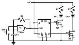
This project involves constructing a coin toss circuit that comprises three main sections: a square-wave oscillator, a JK flip-flop, and two LEDs (one red and one green). The circuit utilizes CMOS digital integrated circuits (ICs) and MOSFET transistors. The...
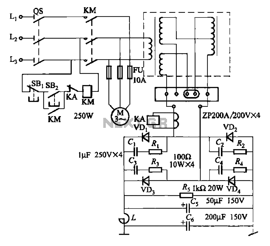
The circuit is designed for inductive loads, specifically within a thyristor power unit, such as a three-phase step-down DC motor speed control and other applications. It is capable of delivering sufficient output power to trigger a thyristor rated at...
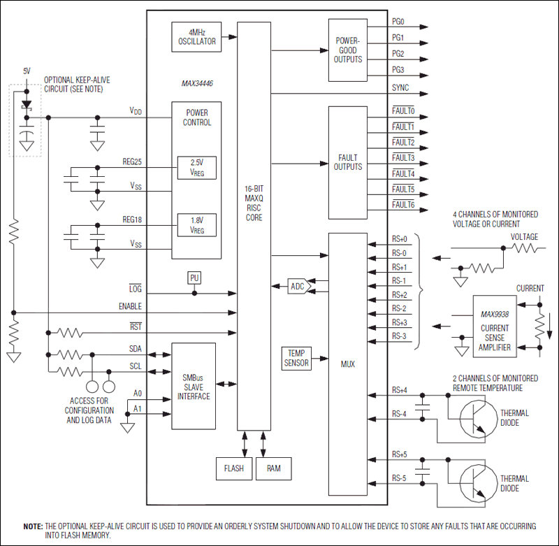
The MAX34446 data logger for power supplies is capable of monitoring voltages for overvoltage and undervoltage conditions, as well as overcurrent and overtemperature situations. The device continuously checks user-programmable thresholds. The MAX34446 is an advanced monitoring solution designed for power...
After restructuring the AC and DC arc welding machine circuit on the BX series AC arc welder by installing a rectifier device, it can be converted into an AC and DC arc welding machine. This restructuring results in a...