
Bedini Self Oscillator High Voltage Output
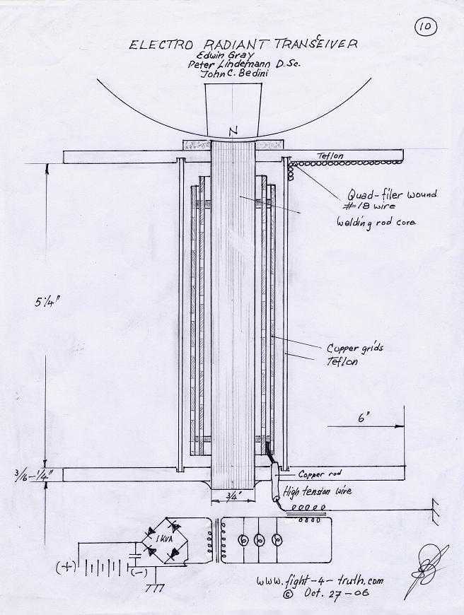
The circuit design described integrates several innovative components to achieve efficient energy generation and utilization. The Tesla pancake coil, known for its ability to produce high voltage and resonant energy, is paired with a bifilar wound coil, enhancing the resonance effect. The series connection facilitates the generation of a sharp gradient discharge, which is critical for creating a vacuum flux necessary for the operation of the CFL.
The Bedini self-oscillating circuit acts as a key component in this setup, providing a means to tap energy from the ignition coil. The connection of the high voltage positive to a modified CFL bulb indicates a departure from conventional lighting methods, allowing for enhanced brightness due to the unique energy harvesting approach. The use of a copper tubing primary coil serves to collect radiant energy, a concept that aligns with principles seen in Tesla coil operation but is adapted here for negative current flow.
In terms of safety and circuit protection, the inclusion of a neon bulb at the transistor collector is a prudent measure to prevent damage from unexpected discharge paths. This aspect of the design highlights the importance of safeguarding electronic components in high-voltage applications.
The planned integration of a solar panel will further augment the system's sustainability, providing a renewable energy source for home lighting. The use of RG-6 coaxial cable for the inner windings and copper plumbing pipe for the outer coil is a creative choice that reflects a practical approach to material selection, balancing performance with available resources.
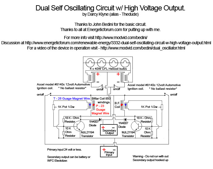
Overall, this circuit exemplifies a blend of traditional electromagnetic principles with modern adaptations, aiming for high efficiency and sustainability in energy use. Future enhancements, such as the automatic battery swapping circuit, suggest ongoing development and optimization of this innovative energy solution.I hook up a tesla pancake coil in series with my bifilar wound coil to generate the resonance and the sharp gradient discharge that creates a vacuum flux. I run the CFL on about. 07amps @12. 42volt + 0. 8694 watts! Around the bifilar pancake coil, I have also placed what would normally be a primary discharge coil (of tesla pancake) made of 1/2" plumbing copper tube that runs around it.
The bedini self oscillating circuit is being tapped at the collector to the neg of the ignition coil. The high voltage + is connected to a 20 watt CFL bulb with the internal circuitry removed and the negative goes to one side of the copper tubing primary of the pancake.
The copper primary is gathering up radiant energy in the form of negative current (opposite to a tesla coil) and increasing both brightness and efficiency of the light. This is a win / win situation. (NOTE: the schematic shown actually has 2 self resonating circuits in it, a mirror image of the left to the right.
In video i`m only using one such circuit. Also a neon bulb should be shown at the collector to the emitter of the MJL21194 transistor to protect the circuit should a discharge path to the secondary battery or CLF bulb happen to disconnect) I will be swapping the batteries back and forth manually as they run and aproach 12. 10volts. In the future a auto swapping circuit will be employed. This test is being done to help exhibit the extreme effiecency of this set up. I will be adding a 300 watt solar panel input to the system to help augment and facilitate lighting for my home.
I already have the 6"x6" cells with triple bus bars to assemble and simply need more time to build the panel. The pancake is comprised of 32 inner windings of RG-6 coaxial cable and 4 windings of 1/2" copper flexible plumbing pipe for the outer, of what would typically be considered primary part of the coil.
I`ve ran the positve on the outer mesh wrap of the RG-6 and the negative it on the interior insulated copper wire at the middle. This seemed to be the best for producing results in my case, but perhaps not in all cases. 🔗 External reference
Related Circuits
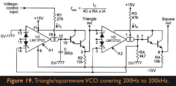
The circuit generates square and triangle waves. There is an inquiry about the possibility of adding a couple of diodes and a potentiometer to enable skewing between triangle-ramp/saw and changing the duty cycle of the square wave. Is it...
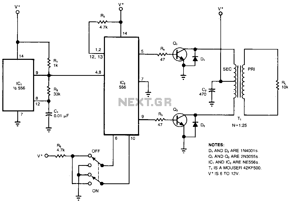
The circuit converts a DC voltage (V+) into a high-amplitude square wave within the audio frequency range. The dual timer, IC2, serves as a cost-effective alternative to traditional transformers for providing complementary base drive to the power transistors, Q1...
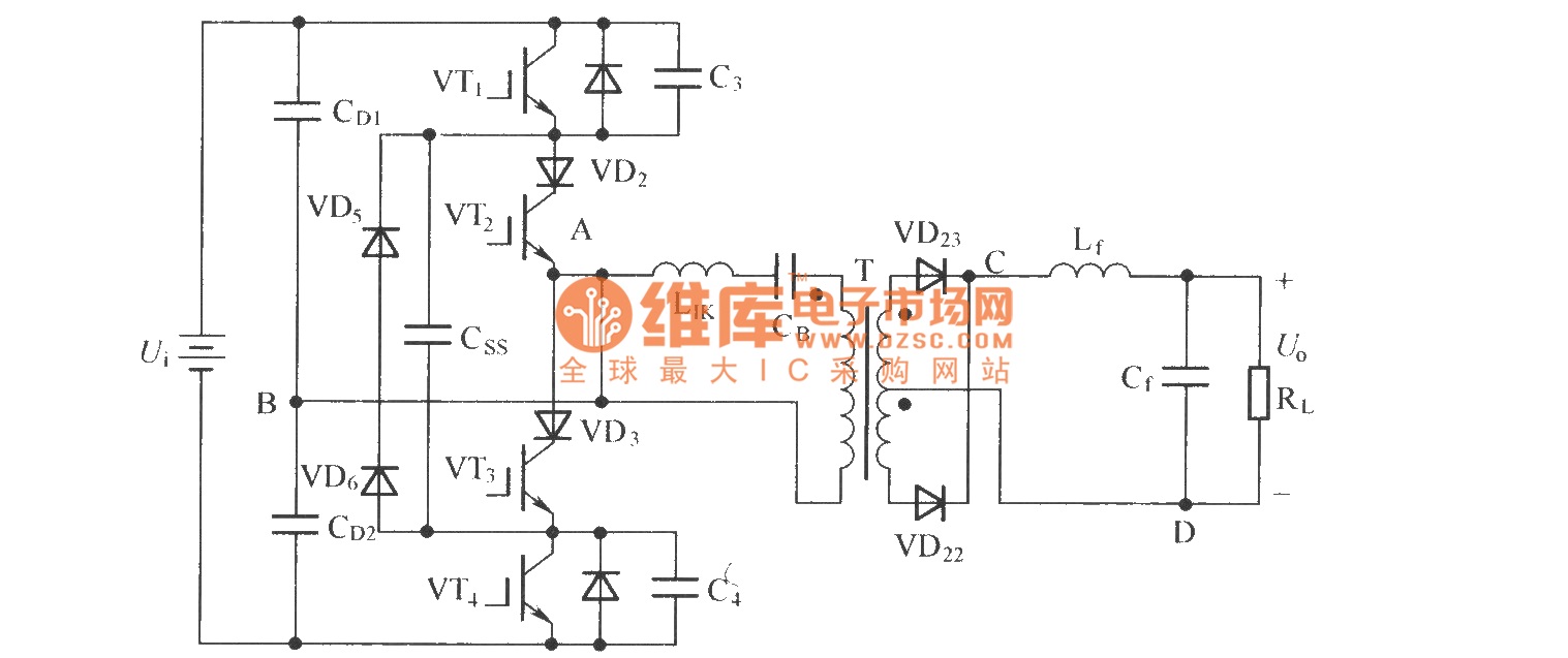
To eliminate circulating current in a zero-voltage switch three-level DC converter during its zero state, a zero-voltage zero-current switch three-level DC converter circuit has been proposed. The primary distinction between this circuit and the standard zero-voltage switch three-level DC...
The power is all in the timed switching process. There are two main principles I use of switching the radiant energy the John Bedini way. First, the SG/SSG, Icehouse unidirectional circuit or John Bedini Monopole with the School Girl...
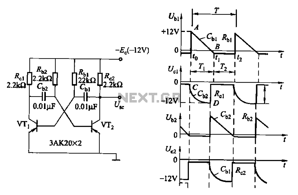
Also known as a no-shot multivibrator, this circuit is often utilized as a pulse (square wave) signal source. The astable flip-flop functions as a strong positive feedback amplifier, with its two branches coupled by an RC timing circuit, resulting...
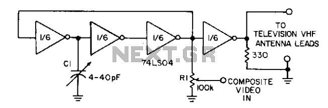
Three gates of a 74LS04 form the oscillator circuit. Capacitor C1 allows fine frequency adjustment to a specific television channel and helps stabilize the circuit. Potentiometer R1 acts as the mixing input and provides adjustment of the contrast ratio...
Warning: include(partials/cookie-banner.php): Failed to open stream: Permission denied in /var/www/html/nextgr/view-circuit.php on line 713
Warning: include(): Failed opening 'partials/cookie-banner.php' for inclusion (include_path='.:/usr/share/php') in /var/www/html/nextgr/view-circuit.php on line 713