
Having a differential amplifier and overcurrent protection for power supply circuit 2
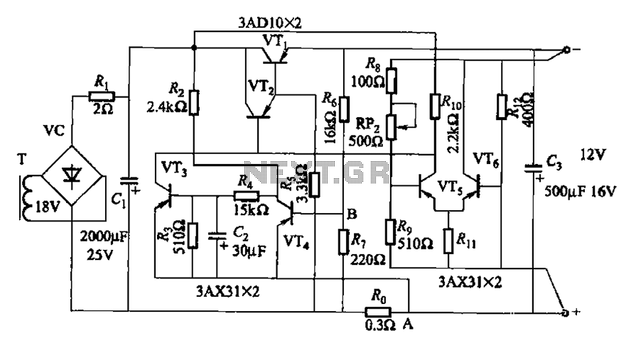
The current protection circuit employs a series of transistors and resistors to safeguard against overcurrent conditions. Transistor VTa acts as the primary control element, while VT4 serves to regulate the output voltage. The sense resistor Ro is critical for detecting current levels; when the current exceeds a predetermined threshold, it triggers the protective measures.
In the event of an overcurrent or short-circuit, the circuit enters a fault state where VT3 remains non-conductive, preventing the output voltage from rising above zero. This state effectively disables the power supply to protect downstream components from damage. To restore functionality, the circuit must be reset. This can be achieved either by manually re-closing the circuit or by integrating a reset button in the collector path of VTa, allowing for a controlled restart.
Capacitor Cz plays a vital role in managing the timing of the circuit's response to power restoration. Upon re-energization, Cz delays the activation of the output voltage until the system is stable, ensuring that VT4 is properly activated to provide the necessary voltage. The resistor Rs is essential for setting the correct bias point for VTi, enabling reliable operation of the circuit under normal conditions.
This design illustrates a robust approach to current protection, combining active and passive components to ensure safe operation in the presence of fault conditions. The careful selection of component values and configurations is crucial for achieving the desired performance and reliability in various applications. By the transistor VTa, VT4, sense resistor Ro-current protection circuit and other components. The power supply after overcurrent or short-circuit fault is eliminated, can not resume normal operation (because VT3 conduction condition has not changed, the output voltage is still zero). To reset, you must re-closing or series in the collector circuit VTa a reset button for the job. Now the capacitor Cz from closing when the power delay action to ensure that the pilot through VT4, in order to establish the output voltage; electrical resistance Rs of the role of the regulator is to ensure that there is an appropriate VTi hope bias.
Related Circuits
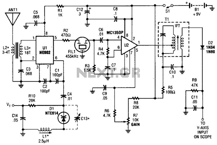
This circuit is designed for monitoring an amateur band or a specific segment of the radio spectrum. It utilizes an NE602 mixer-oscillator chip to generate a 455-kHz intermediate frequency (IF) signal. This signal is amplified by U2 and subsequently...
This circuit turns off an amplifier or any other device when a low-level audio signal fed to its input is absent for 15 minutes at least. Pushing P1, the device is switched on, feeding any appliance connected to SK1....
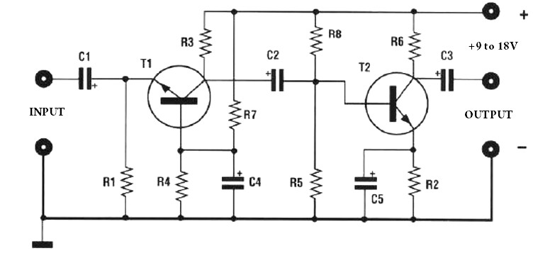
The amplification of this preamplifier is very high. To reduce the amplification, a trimmer resistor R3 in series with a value of 100 ohms should be used. The system can be powered by a voltage ranging from 9 to...
This simple and slightly odd circuit can clearly show the level of the supply voltage (in a larger device): as long as the indicator has good 12 volts at its input, LED1 gives steady, uninterrupted (for the naked eye)...
High-quality, discrete component design for input and tone control modules to complement the 60-watt MOSFET audio amplifier with a high-quality preamplifier design. The circuit design focuses on creating a high-fidelity audio preamplifier that enhances the performance of a 60-watt MOSFET...
The following circuit illustrates a Solar Tracker Circuit Diagram. This circuit is based on the LM339 integrated circuit. Features include a 10nF ceramic capacitor (103z) and a 1MΩ resistor. The Solar Tracker Circuit utilizes the LM339 quad comparator IC to...
Warning: include(partials/cookie-banner.php): Failed to open stream: Permission denied in /var/www/html/nextgr/view-circuit.php on line 713
Warning: include(): Failed opening 'partials/cookie-banner.php' for inclusion (include_path='.:/usr/share/php') in /var/www/html/nextgr/view-circuit.php on line 713