
Solar TrackerCircuit. This Based On The LM339 IC
The Solar Tracker Circuit utilizes the LM339 quad comparator IC to facilitate the tracking of sunlight. The primary objective of this circuit is to maximize the exposure of solar panels to sunlight by adjusting their orientation based on the intensity of light detected. The circuit employs photodiodes or light-dependent resistors (LDRs) as sensors to detect light levels.
When light falls on the sensors, their resistance changes, which in turn alters the voltage levels at the inputs of the LM339. The LM339 compares these voltages and outputs signals that control the movement of motors or servos, enabling the solar panels to pivot towards the light source.
Key components in the circuit include the LM339 IC, which operates with a supply voltage typically between 3V to 36V, allowing it to interface with various power sources. The 10nF ceramic capacitor helps to stabilize the power supply and reduce noise in the circuit, ensuring reliable operation. The 1MΩ resistor is used to set reference voltages and assist in the proper functioning of the comparator inputs.
For optimal performance, the circuit may also include additional components such as potentiometers for fine-tuning the sensitivity of the light sensors and diodes for protection against reverse polarity. The design can be further enhanced by incorporating a microcontroller for more sophisticated tracking algorithms, allowing for improved accuracy and efficiency in solar panel positioning.
This Solar Tracker Circuit serves as an effective solution for increasing the energy output of solar panels by ensuring they are always oriented towards the sun, thereby maximizing solar energy capture throughout the day.The following circuit shows about Solar Tracker Circuit Diagram. This circuit based on the LM339 IC.Features: 10n ceramic capacitor (103z), 1meg .. 🔗 External reference
Related Circuits
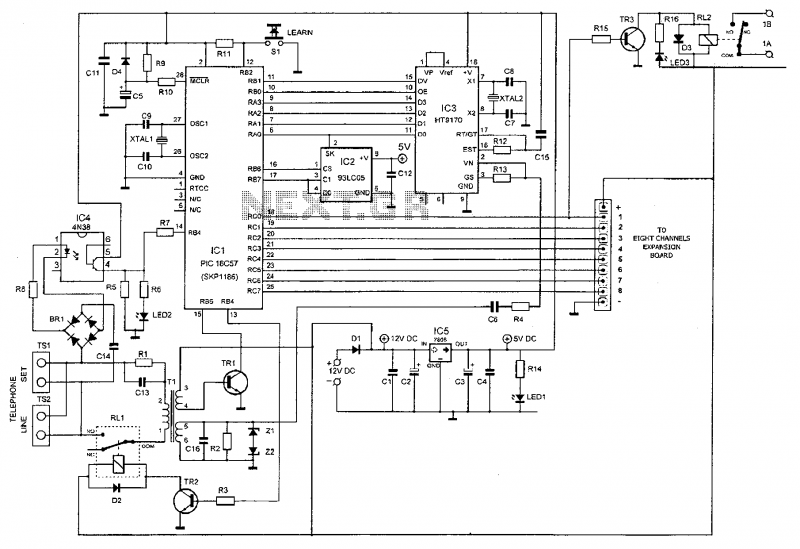
This device enables remote control of various appliances (up to eight with suitable add-on expansion boards) such as lights, water heaters, air conditioning, plant watering systems, alarms, etc., via a relay. It allows users to perform actions such as...
The IQ_Demod project demonstrates the application of the IQ_Demod_Setup and IQ_Demod_Data components within the ADS environment. These components are included in the ADS behavioral model suite, located under the System - Data Models palette. The file "IQ_demod_ckt.dsn" represents the...
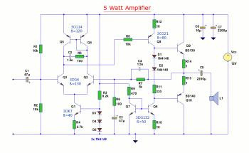
The diagram illustrates a 5W audio amplifier circuit constructed using power transistors BD139 and BD140 for the final amplification stage. This compact amplifier serves as a general-purpose amplifier suitable for applications such as computer audio, radio, MP3 players, and...
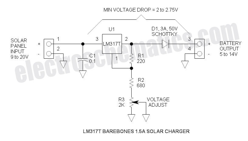
This solar battery charger is a simple and cost-effective project suitable for hobbyists. While it has some limitations compared to other similar devices, it offers several advantages. The charger is designed for lead-acid batteries but can also charge any...
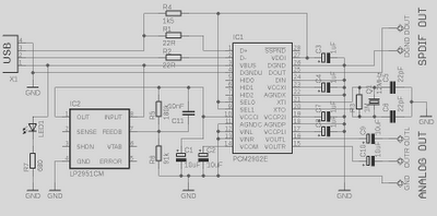
This is a high-quality preamplifier circuit with a built-in USB DAC designed for the Leachamp power amplifier. The schematic is derived from the PCM2902 datasheet. The circuit includes a DAC and ADC, SPDIF output and input, and an HID...
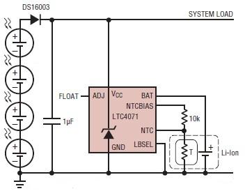
A simple solar-powered battery charger circuit can be designed using the LTC4071 Li-Ion/Polymer Shunt Battery Charger System with Low Battery Disconnect. When VCC reaches the programmed float voltage (4.1V with ADJ floating), the LTC4071 shunts excess current not used...