
Headlights Timer
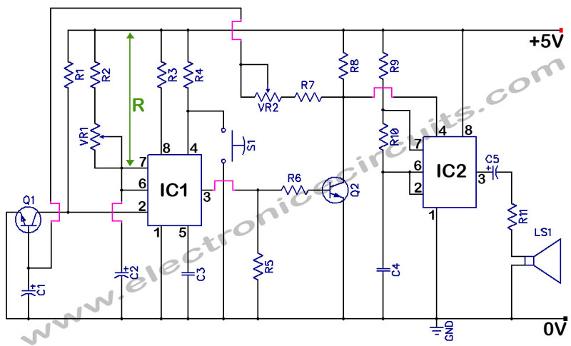
The circuit operates by utilizing a simple timer mechanism that leverages a capacitor, transistors, and a relay to control the headlights. The core components include a 12V battery, a timing capacitor (C1), and two transistors (Q1 and Q2) that function as switches. When switch P1 is pressed, the circuit allows capacitor C1 to charge to the battery voltage. The charging process energizes transistor Q1, which subsequently activates transistor Q2. This activation closes the relay (RL1), allowing current to flow to the vehicle's headlights, thereby illuminating them for the preset duration.
The timer's duration is primarily determined by the discharge characteristics of capacitor C1, which is influenced by the values of the resistor (R1) in the circuit. The relay used (RL1) is capable of handling the current required by the headlights, ensuring reliable operation. As C1 discharges, the voltage across it decreases until it reaches the threshold voltage of approximately 0.7V, at which point the relay deactivates, turning off the headlights.
For the alternative configuration with the interior lamp, the diode (1N4002) plays a crucial role in controlling the timing operation. When the door is opened, the interior lamp provides a voltage that charges C1. The diode prevents C1 from discharging back through the lamp circuit when the door is closed, allowing the timer function to initiate. This modification enhances the convenience of the system by automating the headlight operation based on the vehicle's door status.
Overall, this timer circuit is an effective solution for managing vehicle headlights, providing both safety and convenience when navigating dark areas. Its simple design allows for easy integration into existing vehicle electrical systems, making it a practical enhancement for drivers.This device is a simple timer, allowing to keep on the headlights of your vehicle for about 1min. and 30sec. , e. g. when accessing some dark place, without the necessity of coming back to switch-off the lights. Pushing on P1 allows C1 charging to full 12V battery supply. Therefore Q1 is driven hard-on, driving in turn Q2 and its Relay load. The hea dlights are thus activated by means of the Relay contact wired in parallel to the vehicle`s headlights switch. RL1 remains activated until C1 is almost fully discharged, i. e. when its voltage falls below about 0. 7V. An interesting variation is to use the inside lamp as a command source for the timer. In this way, when the door is opened C1 is charged, but it will start to discharge only when the door will be closed, substituting pushbutton operation.
To enable the circuit acting in this way, simply connect the cathode of a 1N4002 diode to R1-C1 junction and the anode to the "live" lead of the inside lamp. 🔗 External reference
Related Circuits
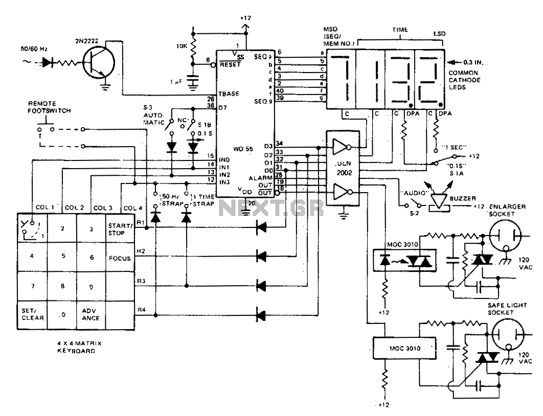
The darkroom timer/controller utilizes a minimal number of external components, including a display, a digit driver, a keyboard, and output switching devices. A 4-digit common-cathode LED display is preferred for use in darkroom settings. The time base is generated...
The objective of this circuit is to power a lamp or other device for a predetermined duration (30 minutes in this instance) and subsequently turn it off. This functionality is particularly beneficial for reading in bed at night, as...
How many individuals have experienced legitimate issues with the 555 timer? It can be inferred that these problems often involve the reset line, specifically pin 4, which must be set high before operation. The 555 timer IC is a versatile...
555 Timer with Audio Alarm Circuit. This circuit serves as a straightforward electronic timer equipped with an audio alarm feature. The 555 timer is a versatile integrated circuit widely used in various timer, delay, pulse generation, and oscillator applications. In...
This is a programmable clock timer circuit that utilizes individual LEDs to indicate hours and minutes. Twelve LEDs can be arranged in a circle to represent the 12 hours of a clock face, and an additional 12 LEDs can...
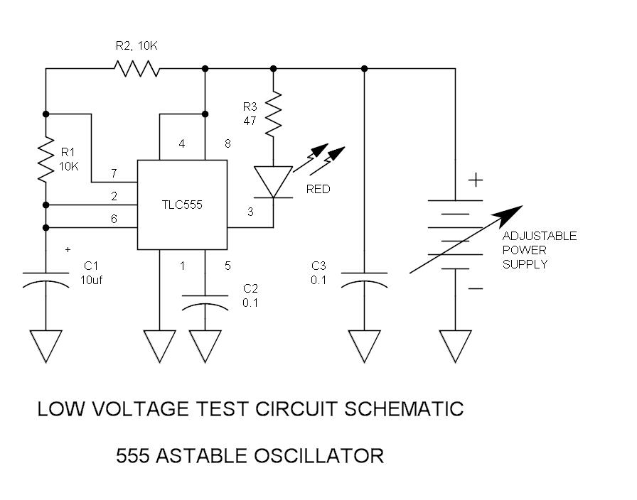
The integrated circuit (IC) tester featured on this website is specifically designed for the LM555 timer IC. This circuit is utilized for testing the functionality of the timer IC, and it includes a circuit diagram along with techniques for...