
Quirky 555 Timer Reset Function
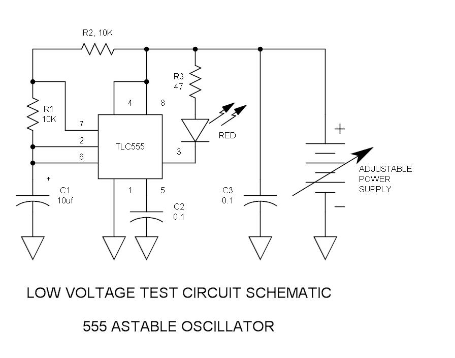
The 555 timer IC is a versatile device widely used in various electronic circuits for timing, pulse generation, and waveform shaping. It operates in several modes, including monostable, astable, and bistable configurations. One common issue that users encounter is related to the reset functionality, which is controlled by pin 4 of the IC.
In the standard 555 timer configuration, pin 4 serves as the reset pin, which allows for the interruption of the timing cycle. For proper operation, this pin must be held high (typically connected to Vcc) to ensure that the timer can function correctly. If pin 4 is inadvertently pulled low, the timer will reset, causing the output to go low regardless of the state of the other input pins. This behavior can lead to unexpected results in circuits where precise timing is critical.
To mitigate issues associated with the reset line, it is advisable to include a pull-up resistor connected to pin 4. This resistor ensures that the reset pin maintains a high state unless intentionally driven low by an external signal. Additionally, careful attention should be given to the layout of the circuit to minimize noise and interference that could inadvertently affect the reset line.
In summary, while the 555 timer is a robust and widely used component in electronic design, attention to the reset functionality is crucial for reliable operation. Properly managing pin 4 can prevent common issues and enhance the overall performance of circuits utilizing this versatile timer IC.How many have had legitimate problems with the 555 timer? Let me guessit involved the reset line, did it not? We all know that pin 4 must be set high befo.. 🔗 External reference
Related Circuits
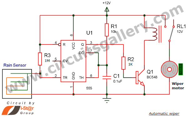
Have you seen Audi, Lexus, or Ford rain-sensing wipers and wondered how they operate in these vehicles? They are controlled by sensors located at the center of the windscreen, which detect raindrops and activate the wiper motor. The functioning...
The purpose of this circuit is to power a lamp or other appliance for a given time (30 minutes in this case), and then to turn it off. It is useful when reading at bed by night, turning off...
This timer is designed to automatically switch off a portable radio after a set period, allowing users to relax without worrying about battery drain. Resistor R1 and capacitor C1 create a long time constant. When switch P2 is momentarily...
Do not use the on-board relay to switch mains voltage. The board's layout does not provide adequate isolation between the relay contacts and the low-voltage components. If mains voltage switching is required, mount a suitably rated relay in a...
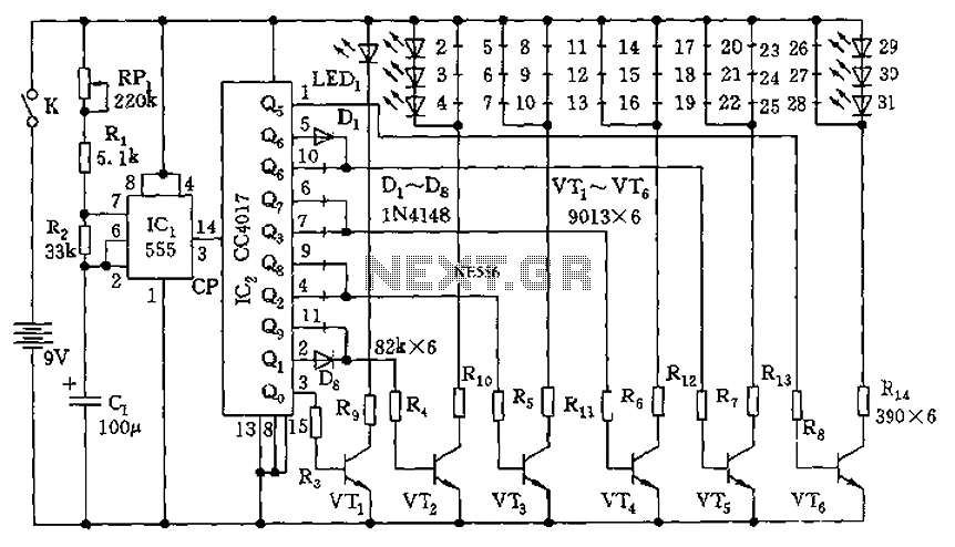
The circuit features a clock pulse generator and a pulse distribution circuit that drives the display circuit. It consists of a 555 timer and resistors RP1, R1, R2, along with capacitor C1, forming an astable multivibrator. The oscillation frequency...

The circuit is constructed using the ICM7217 integrated circuit from Intersil, which features a CMOS up/down counter with a four-digit display. The clock generator circuit, IC3, produces a square wave clock signal with a period of one second, available...
Warning: include(partials/cookie-banner.php): Failed to open stream: Permission denied in /var/www/html/nextgr/view-circuit.php on line 713
Warning: include(): Failed opening 'partials/cookie-banner.php' for inclusion (include_path='.:/usr/share/php') in /var/www/html/nextgr/view-circuit.php on line 713