heat temperature sensor alarm

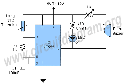
This is a straightforward and easy-to-construct heat or temperature sensor alarm circuit. A notable feature of this circuit is its ability to emit a beep sound and flash an LED in response to temperature changes.
The heat or temperature sensor alarm circuit operates by utilizing a temperature sensor, such as the LM35 or a thermistor, which detects variations in temperature. The sensor is connected to a comparator circuit that compares the input voltage from the sensor against a predetermined reference voltage. When the temperature exceeds a specific threshold, the output of the comparator changes state.
The output from the comparator can be used to drive a transistor that controls an alarm system, typically consisting of a piezoelectric buzzer for sound output and an LED for visual indication. The buzzer produces a beep-beep sound, signaling that the temperature has surpassed the set limit, while the LED flashes to provide a visual alert.
To enhance the circuit's functionality, a potentiometer can be integrated to allow for adjustable temperature thresholds. This enables customization of the alarm activation point based on specific requirements. Additionally, a resistor may be included in series with the LED to limit the current and prevent damage to the component.
Power supply considerations are crucial, as the circuit typically operates on a low voltage, often between 5V to 12V, depending on the components used. Proper layout and placement of components on the PCB or breadboard are essential for minimizing noise and ensuring reliable operation.
In summary, the heat or temperature sensor alarm circuit is a practical and effective solution for monitoring temperature changes, providing both auditory and visual alerts when specific temperature thresholds are exceeded.Here is a simple and easy to make heat or temperature sensor alarm circuit. A good feature of this circuit is that it will produce beep-beep sound and flashes an LED according to the temperature.. 🔗 External reference


