
SIREN ALARM SIMULATES STAR TREK RED ALERT
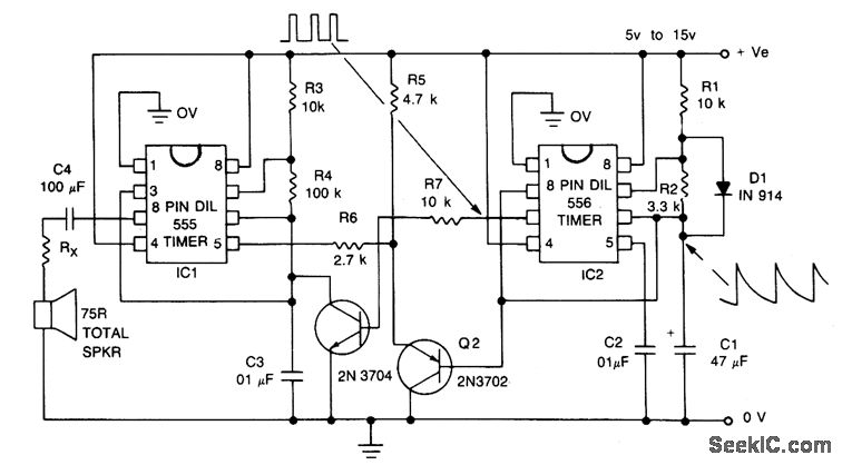
The described signal exhibits a repetitive waveform characterized by a low-to-high frequency transition. The rising edge of the signal occurs over a defined duration of 1.15 seconds, indicating a linear or exponential increase in frequency, depending on the specific application requirements. The high-frequency plateau achieved at the peak of this transition is maintained momentarily before the signal enters a brief pause lasting approximately 0.35 seconds. This pause serves as a reset period before the cycle recommences, allowing for potential applications in pulse modulation or frequency-shift keying.
In a practical electronic circuit design, this type of signal can be generated using a combination of oscillators and timers. A function generator or a microcontroller programmed with a timer interrupt could be employed to create the desired frequency modulation. The oscillator would be responsible for producing a low-frequency signal, which can be modulated to rise to a high frequency using a controlled ramp function. The timing for the rise and pause can be accurately managed through digital signal processing techniques or analog timing circuits, ensuring precise control over the frequency transitions.
Furthermore, filtering may be required to smooth the transitions between frequency states, preventing abrupt changes that could introduce unwanted harmonics or noise into the signal. This can be achieved using low-pass filters designed to work at the expected frequency range. The implementation of this signal pattern could find applications in various fields, such as communication systems, signal processing, or audio modulation, where controlled frequency variations are essential for effective data transmission or sound synthesis.The signal starts at a low frequency, rises for about 1. 15 seconds to a high frequency, ceases for about 0. 35 seconds, then starts rising again from a low frequency, and so on ad infinitum. 🔗 External reference
Related Circuits
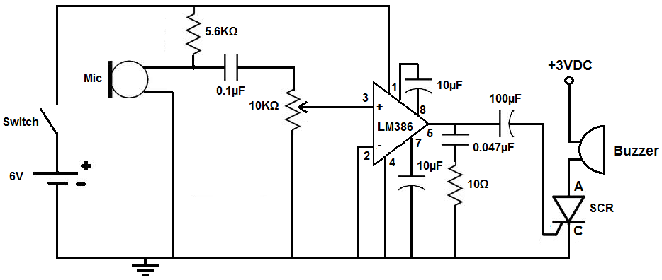
This circuit is designed to activate an alarm when it detects sound above a specified threshold. The alarm serves as a notification for any sound in areas that are typically quiet, such as quiet zones. Under normal quiet conditions,...

In this circuit, the alarm activates under four different conditions: 1. When light falls on LDR1 (located at the entrance). 2. When light on LDR2 is obstructed. 3. When door switches are opened or a wire is cut. 4....
Before starting a project of this nature, it is crucial to remember that mains voltage is hazardous. If there is any uncertainty regarding the procedure, it is advisable to consult someone with the appropriate skills or refrain from proceeding...
This circuit automatically activates a night lamp when the bedroom light is turned off. The lamp stays illuminated until the light sensor detects daylight in the morning. A super-bright white LED is utilized as the night lamp, providing bright...
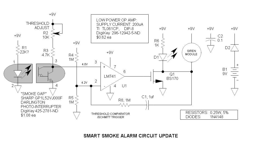
The original smoke alarm circuit has several issues that have left hobbyists and students dissatisfied. Instead of trying to resolve its numerous problems, an updated version has been created using the well-known LM741 op-amp. This new design is simpler,...
This circuit illustrates the NE555 timer used in a light-sensitive alarm sensor circuit diagram. Features include the ability to detect a sudden shadow falling on the sensor. The NE555 timer is a versatile integrated circuit widely utilized in various timing,...