
mosfet Turning a microcontroller on with a flip flop
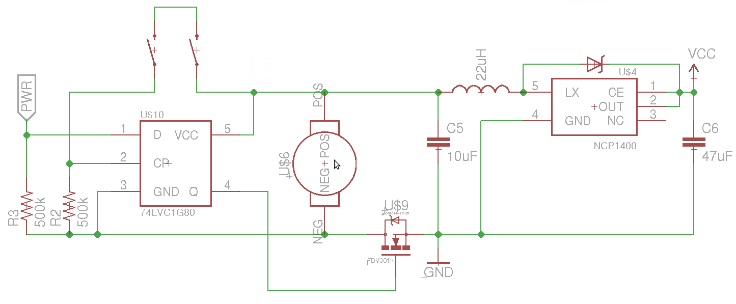
The circuit involves a high-side switch configuration to maintain a stable ground reference for the microcontroller and associated components. The PWR pin is controlled through a flip-flop, which is triggered by the state of the switches. When the switches are pressed, the flip-flop's output transitions, allowing the uC to power on or off accordingly. The use of a MOSFET in the high-side switch configuration ensures that the ground reference remains intact, preventing the PWR pin from floating and thus avoiding indeterminate states.
The suggestion to utilize a divide-by-two flip-flop configuration is significant for achieving toggle functionality. This approach allows the circuit to maintain a stable output state with minimal interference from switch bounce, which could otherwise lead to erroneous toggling. The inclusion of a capacitor for debounce filtering is essential; it smooths out the transitions and mitigates the effects of mechanical bounce in the switches, ensuring reliable operation.
In automotive applications, additional considerations must be taken into account. The circuit design should comply with automotive standards, which require protection against voltage spikes and load dumps. Implementing Schmitt trigger inputs for switch signals is advisable, as they provide noise immunity and ensure clean transitions through the undefined threshold states. This is particularly crucial in environments where electrical noise may induce false triggering.
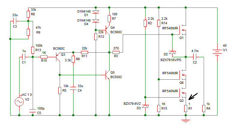
Overall, the circuit must be designed with careful attention to grounding, debounce filtering, and protection mechanisms to ensure reliable operation of the microcontroller and associated load under varying conditions. Proper implementation of these principles will enhance the robustness and durability of the design in practical applications.The goal is to be able to turn on and off the load (an 8051 based uC) by pressing both switches. When the uC turns on, it sets PWR high, and then when the switches are pressed again, pin 4 of the flip flop goes low, turning off the boost regulator and uC. The issue that I`ve been having is that in the off setting (pin 4 low), the PWR pin is held a t about half the battery voltage, which prevents me from turning the device on. My best guess is that because the uC no longer has a valid ground reference to the battery (the MOSFET is not conducting), the PWR pin is being held in an indeterminate state because of a small current flow through the uC. Is this correct Why exactly is it bad, and what would be a better way of doing it I was referencing this post when I designed the circuit.
Carson Darling Sep 25 `12 at 17:57 Your ground is your reference, and should always and everywhere be the same. If you place a switch in it you have two grounds, and you lose your reliable reference. Solution: high-side switching, before the inductor. stevenvh Sep 25 `12 at 18:01 @stevenvh I think that while they can be answered in the same way, they are different.
As I see it, this one is about switching the power to the uC, while the other one is about switching a load from the uC. clabacchio™ Sep 27 `12 at 7:59 If you really want a toggle switch without using the micro, then you need to make the FF operate as a /2 counter where Din is connected to Qbar out rather than V+.
Adding a small 0. 01 uF cap to the 500K to gnd will give you 10mS debounce filtering. You can always increase that make that bigger for bigger switch bounce times and/or prevent fast toggling intervals. (whispers. BTW Old English cars had positive grounds, and worked ok, but the reason switched grounds are a bad idea, is it shows you may not be aware yet that if interface signals get driven below the raised ground.
somewhere else. , a latch-up effect may occur, (turning the chip into a lossy SCR fuse across the power supply) Although limited diode clamp protection is included, there are risks if the interface spikes faster than the internal protection diode can respond. ) The FF is powered directly from the battery, and I definitely need a filtering cap on Vcc for the FF.
With the capacitor giving debounce filtering, wouldn`t that cause issues as the voltage goes through the invalid input section of the FF Carson Darling Nov 2 `12 at 20:03 There are alot of assumptions and concerns with the simplified schematic w. r. t. fault conditions blowing out the FF chip. Automotive design standards require at least 24v to -12V protection and load dump protection, in case of jump starts.
But input filtering is mandatory on switches and Schmitt trigger inputs are preferred. " Transition thru the "Invalid input section" means thru the undefined threshold state. As long as Cp is monotonic, it will detect only one edge, thus Schmitt input hysteresis is pref. in noisy env. and D to Qbar gives a toggled output with one switch. Tony Stewart Nov 2 `12 at 22:13 Cap on Cp switched input will provide instant transition on 1st contact bounc and slow decay during subsequent bounces. THen slow decay on release should not retrigger it. RC> 10ms typ. depending on swtich. Tony Stewart Nov 2 `12 at 22:17 🔗 External reference
Related Circuits
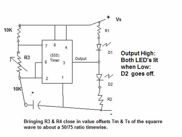
The output signal is configured to go high for approximately 0.5 seconds and then low for around 1.33 seconds. However, there is an issue present. The circuit in question likely employs a timing mechanism to achieve the specified output signal...
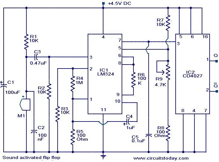
This circuit allows the output pins of a Flip Flop IC to be toggled using sound. A condenser microphone captures the sound, and the first two operational amplifiers in the LM324 IC amplify the signal. The third operational amplifier...
The WS2512-TR1G is a Wide-band Code Division Multiple Access (WCDMA) Power Amplifier (PA) designed as a fully matched 10-pin surface mount module, specifically developed for WCDMA handset applications. This power amplifier module operates within a frequency range of 1920-1980...
Increasing the quiescent current (Iq) will result in more power output at 4 ohms. It is understood that decreasing the supply voltage affects performance. Increasing the quiescent current (Iq) in a circuit can lead to enhanced power output, particularly when...
The SP6691 circuit is designed to provide a high output voltage using a lower voltage boost regulator by incorporating a charge pump circuit. This configuration can convert a standard 30V boost regulator into a 60V boost regulator if necessary....

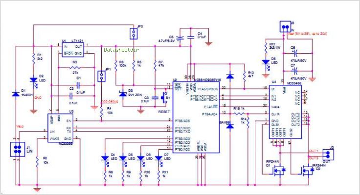
A mobile-controlled robot is a mobile device that offers extensive wireless control capabilities to the robot, as long as the cell phone remains within signal range. The mobile-controlled robot operates through a wireless communication interface, typically utilizing Bluetooth or Wi-Fi...