
Homemade Metal Detector Kit
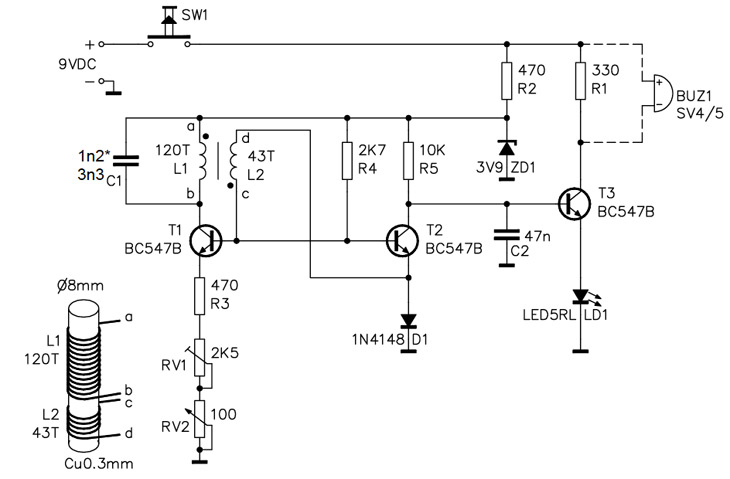
The metal detector project described utilizes a simple yet effective circuit design that incorporates a metal detection mechanism, an LED indicator, and a user-friendly assembly process. The core of the device is built around a 200 kHz oscillator circuit, which is essential for detecting metallic objects by inducing voltage changes in the surrounding environment. The oscillator is formed by capacitor C1 and a primary coil with 120 turns, which generates a high-frequency signal.
The output from the oscillator is fed to a transistor (T2), which acts as a switch to control the LED indicator. When metal is detected, the induced voltage causes T2 to turn on and off, signaling the presence of metal through the LED. The second transistor (T3) is responsible for controlling the LED based on the voltage levels detected by T2. The use of silicon and Zener diodes within the circuit ensures proper voltage regulation and signal integrity.
The design emphasizes user safety and ease of assembly. The enclosure chosen not only protects the internal components but also facilitates portability, which is crucial for field use. The detailed instructions for drilling and aligning holes in the enclosure demonstrate a practical approach to ensure that all components are securely housed and accessible.
In summary, this metal detector kit combines essential electronic components and thoughtful design considerations to create a reliable tool for detecting metal objects in various environments. The careful assembly instructions and troubleshooting tips provided enhance the user experience, making it a suitable project for electronics enthusiasts.A simple home project can turn catastrophic fast if you come up against an electric cable, gas and water pipes, or your central heating system. With a handy metal detector you can check beforehand whether there are metal objects in a wall, ceiling or floor.
An LED indicates if a metal object is in the vicinity and keeps your simple home projects, simple and safe. When wrapping the coils, do not worry about looks. There is not enough room on the core to keep the coils from overlapping. However, make sure you wrap each one in the same direction. When you solder the coil onto the PC board, make sure to strip the insulation off the ends of the coil. Either a razor blade or a fine-toothed file works great for this. For this kit, there are two types of diodes: Silicon (P/N 179215) and Zener (P/N 782788). Because they look the same, read the outer casing to be sure that you are putting in the right diode.
The silicon diode has 4148 on it, while the Zener`s casing reads 3V9. I mistakenly exchanged the diodes, and it took a lot of time to figure out I had put them in the wrong holes. Also, make sure to match up the band on the diode to the band on the silkscreen. If you suspect a misplaced or bad diode, measure the forward voltage drop across them, which should be about 0.
6V for each diode. The reverse breakdown voltage for the Zener diode should be about 3. 9V. Be sure to match the flat side of the LED with the flat side in the picture on the silkscreen. Since it can be hard to see the flat side, the short lead on the LED indicates the flat side. If the LED is not turning on, measure the voltage drop across the LED. If it is 0 Volts, you probably have put the LED in the wrong way. The Metal Detector Kit needs a case, especially if you plan to move it around. I chose a Serpac enclosure (P/N 374635) because of its included battery bay, which keeps the battery as far away from the coil as possible. Below details the assembling of this box. There are no mounting holes in the PC board, so I found the spot with the most space and made a hole and held the board to a bright light to see the traces.
This ensures that you are not drilling through any of them. The kit provides a small tube that fits into the large potentiometer for easy calibration. Enclosing the kits means you`ll have to drill to accommodate that tube but lining up holes in both sides of the enclosure can be tricky. To make sure my drilled holes lined up properly, I put four nails through the screw holes on one half of the enclosure (see picture).
Then I dusted the top of the calibration tube with chalk dust, positioned the second half of the enclosure onto the nails, and pushed. The result was a chalk mark showing where the tube was located and therefore where to drill. I used a 1/4-inch drill bit for this hole, and the tube fits quite snugly. Since the power button is rectangular, I used a 3/8-inch drill-bit, and a small file to cut the hole.
It is not perfectly square, but you can comfortably push the power button down. To make the hole for the light from the LED to escape, I put a small piece of drinking straw on the LED and used the aforementioned nail trick. Another way to have done this would have been to extend the LED so it sticks through the hole. One of the problems I had was getting the LED to turn off. I discovered that I had switched the diodes. This troubleshooting process can be made easier if you have some understanding of how the circuit works: C1 and the 120-turn primary create a 200 kHz oscillator inducing varying voltages on T2 (like in the oscillator picture to the right).
At the positive peaks of the oscillation, T2 is turned on causing the voltage on the collector of T2 to drop. These negative excursions also bias the base of T3, which causes T3, and therefore the LED, to turn off.
The reason why the LED does not turn on and off is that C2 and R5 create an integrator that integrates all the 🔗 External reference
Related Circuits

The peak detector tracks and holds the highest output voltage from a transducer by utilizing the charge-storing capability of a capacitor. Initially, the voltage at the inverting input of the comparator is at ground level. When a small voltage...
This simple water detector circuit utilizes alternating voltage to prevent electrode corrosion. It is easy to construct and employs N1 as a trigger Schmitt gate to generate the AC signal. When a conductive substance, such as an aqueous solution,...

A heat-sensitive sensor can be utilized to create a direction detector. This type of sensor responds to minimal heat. The specific sensor used in this design features a sensitive surface that has been divided into two sections. Consequently, it...
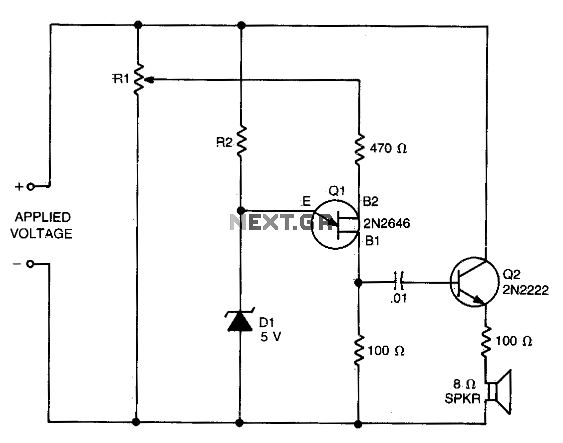
The values of R1, R2, and D1 are selected based on the voltage applied. Using a 12-volt battery, R1 is set to 10 kΩ, R2 to 5 kΩ, and D1 is a 5-volt zener diode or a string of...
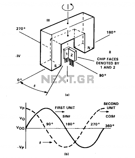
The figure illustrates two TL3103 linear Hall-effect devices utilized for detecting the angle of rotation. The TL3103 devices are positioned in the gap of a U-shaped permanent magnet. The angle formed between the south pole and the chip face...

This circuit determines whether multiple inputs in a digital input group are active. It provides a digital measurement of the number of active inputs and allows for the establishment of a threshold for majority-decision applications. This means it can...
Warning: include(partials/cookie-banner.php): Failed to open stream: Permission denied in /var/www/html/nextgr/view-circuit.php on line 713
Warning: include(): Failed opening 'partials/cookie-banner.php' for inclusion (include_path='.:/usr/share/php') in /var/www/html/nextgr/view-circuit.php on line 713