
Hi-Fi Headphone Amplifier
The headphone amplifier circuit is designed to enhance audio signals from preamplifiers to drive headphones efficiently. Key features include a low output impedance, which is crucial for driving multiple pairs of headphones without significant degradation in audio quality. The active gain stage employs a logarithmic response, ensuring that volume adjustments are perceived as smooth and natural, improving user experience.
The circuit incorporates a potentiometer that does not affect the logarithmic gain characteristics, allowing for consistent audio performance across different settings. This feature is particularly beneficial in maintaining excellent channel tracking, ensuring that both left and right audio channels are balanced regardless of volume level. Additionally, the design minimizes output noise as the gain is reduced, enhancing the overall sound clarity, especially at lower volumes.
For integration within a larger audio system, the headphone amplifier can be permanently connected between the preamplifier and power amplifier. This configuration allows it to serve as a dedicated headphone output without interfering with the main audio signal path. Alternatively, it can function as a standalone unit, providing flexibility for various audio setups.
The inclusion of an input relay is a notable design consideration. This relay is triggered by auxiliary contacts on the headphone sockets, allowing for automatic switching between headphone and speaker outputs. The relay is controlled by a transistor driver, which introduces a small delay to prevent popping sounds during switching, thereby protecting both the headphones and the amplifier.
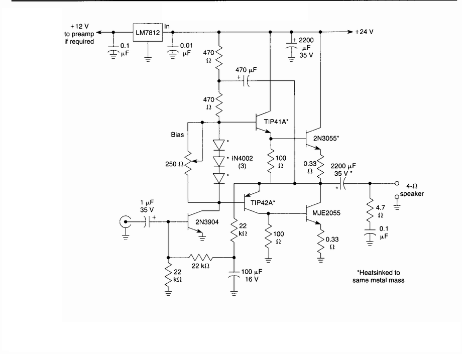
Overall, the headphone amplifier circuit is engineered for high fidelity and versatility, making it an excellent addition to any audio system requiring headphone connectivity.This design for a headphone amplifier arose after the purchase of commercial equipment with separate pre and power amplifiers without a headphone output. Its advantages are ... * low output impedance to drive several pairs of phones * the active gain stage is, almost, perfectly logarithmic and ...
o is independent of the absolute value of the pot o has excellent channel tracking o the O/P noise reduces with gain reduction. The intention is to permanently insert the headphone amp between pre and power amps, although it can be used as a stand-alone item. The input relay is operated by auxiliary contacts on the headphone sockets through a transistor driver (with a small delay)
🔗 External reference
Related Circuits
This is a schematic diagram of a video amplifier circuit with bi-phase output. The bi-phase output generates both positive-going and negative-going signals, enabling balanced signaling. The primary component of this circuit is the LM1201. In this configuration, the inverted...

This is a simple headphone amplifier circuit designed to drive headphones when a music player lacks sufficient power. The circuit is straightforward and utilizes only three transistors. The first transistor, Q1 (BC 239), along with its associated components, functions...

The genesis for this hybrid electrostatic headphone amplifier occurred when I was in Hawaii on vacation, at a fancy hotel on Maui. Sitting at the bar on the beach, drinking "Blue Hawaiis," I drew the schematic for the amp...
This circuit deactivates an amplifier or other devices when a low-level audio signal at its input is absent for at least 15 minutes. By pressing P1, the device is activated, supplying power to any appliance connected to SK1. The...
This circuit is a general-purpose 10-W audio amplifier designed for moderate-power public address (PA) systems or as a modulator in an AM transmitter. By applying higher voltages and adjusting the bias resistors, it is possible to achieve output power...
Microphone amplifier schematic diagram. This circuit has been tested with three microphones: one from SONY and two from Chinese manufacturers, and it operates successfully with all. When assembled correctly, the device functions immediately without the need for tuning. The microphone...