
High pressure natural gas shutoff valve drive circuit diagram
The driver circuit for the high-pressure natural gas shut-off valve is designed to manage the flow of natural gas in a dual-fuel engine operation. The circuit employs solid-state relays for reliable switching, minimizing mechanical wear and improving response times. The operational logic is dictated by a series of inverters (U2, specifically 7404), which play a critical role in signal processing.
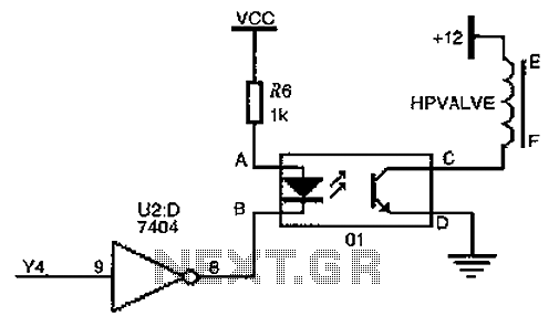
In the active state, when the fuel switching mechanism is engaged, the logic section outputs a high signal to Y4, which allows the solid-state relay to conduct. This conduction enables the output terminal to provide a 12V supply to the solenoid valve (HPVALVE). The solenoid valve is critical for controlling the gas flow into the engine, ensuring that it only receives gas that has been properly regulated by the pressure reducer valve.
The circuit's design incorporates fail-safe features. When the logic section determines that the electromagnetic valve should close, it sets Y4 to a low state. The inverter then processes this signal, resulting in point B being driven high. This change in state effectively cuts off current to the solid-state relay, deactivating the output terminal and allowing the solenoid valve to return to its default closed position, aided by a spring mechanism. This ensures that in the event of a fault or loss of control signal, the gas flow is automatically halted, enhancing safety during operation.
Overall, this circuit is a robust solution for managing high-pressure natural gas in dual-fuel applications, combining effective logic control with reliable solid-state switching to ensure safe and efficient operation. As shown for the driver circuit high pressure natural gas shut-off valve, the device 01 for the solid state relays. When the engine is in dual-fuel mode of operation, the opera tion of the fuel switching mechanism, the logic judging section instructs so Y4 1, is high by U2 (7404, inverters), the electric point B UB low, surface potential UA point a to point B than high, then the input of the solid state relay is turned on, the output terminal is also turned on. The output of CD Once connected, the solenoid valve HPVALVE ends will add 12V rated working voltage, high-pressure natural gas before the pressure reducer valve open, gas enters the engine under reduced pressure.
When the instruction issue logic portion of the electromagnetic valve is closed, Y4 0, after the inverter, B is high, UA UB, no input current through the solid state relay, the output terminal is not turned on, the solenoid valve recovery normally closed by the spring force.
Related Circuits
This circuit is a conventional Pierce type oscillator that utilizes a JFET. It operates with fundamental mode crystals and exhibits good performance and reliability when a low noise JFET is employed. The feedback is regulated by the capacitance of...
A basic digital voltmeter circuit utilizing the Harris Semiconductor ICL7107 is presented. It operates within a 2-V range. Calibration involves applying a known voltage of 1.2 V to the input and adjusting resistor R3 to achieve an accurate reading...
The first option is a Zener diode. There are several 2.2V Zener diodes available that could adequately protect the capacitor. However, a significant drawback is that half the energy may be wasted across the diode short. The question arises...
Here is an updated schematic featuring the RF Solutions receiver along with several minor additions. The design includes additional circuitry to manage the signals effectively. The updated schematic incorporates an RF Solutions receiver, which is essential for receiving radio frequency...
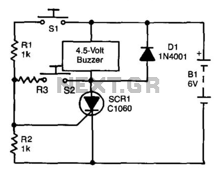
A self-interrupting device connected to a voltage source operates as a switch that continuously opens and closes; thus, the circuit does not latch in the conventional manner, allowing the alarm to function only while switch SI is closed. Due...
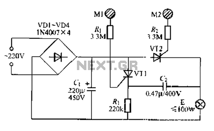
A circuit configuration features a relatively new strong key touch-state switch. Normally, the thyristors VT1 and VT2 are in the off-state, allowing minimal current to pass through the lamp F. At this point, the capacitance C comes into play....