
high stability voltage source model
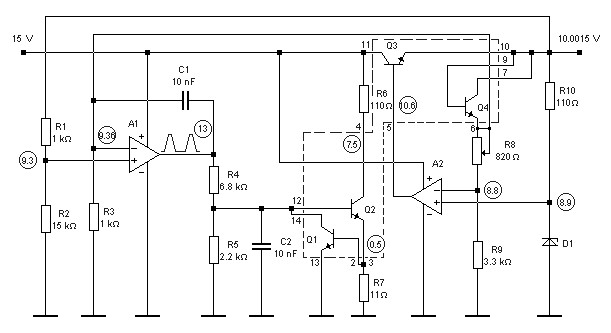
The 10V high-stability voltage source is designed to provide a reliable and consistent output voltage, making it suitable for various electronic applications that require precision power supply. This model typically employs a linear voltage regulator or a precision reference voltage IC to achieve the desired stability and low output noise.
The circuit may include essential components such as resistors, capacitors, and diodes that work together to filter and stabilize the output voltage. The input voltage is usually higher than 10V, allowing the regulator to maintain a stable output while dissipating excess voltage as heat.
In addition, feedback mechanisms are often integrated into the design to monitor the output voltage and adjust the regulation as needed, ensuring minimal fluctuations under varying load conditions. Capacitors may be utilized at both the input and output stages to smooth the voltage and reduce ripple, enhancing the overall performance of the power supply.
Thermal management is also a critical factor in the design, with heat sinks or thermal pads employed to dissipate heat generated by the voltage regulation process. This ensures the longevity and reliability of the power supply.
Overall, the 10V high-stability voltage source is an essential component in many electronic systems, providing a dependable power supply that meets the stringent requirements of modern electronic devices.10V High-Stability Voltage Source Model power supply. Go to that page to read the explanation about above power supply related circuit diagram. 🔗 External reference
Related Circuits
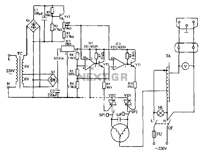
Automatic AC voltage regulator circuit The automatic AC voltage regulator circuit is designed to maintain a stable output voltage despite fluctuations in the input voltage. This circuit is essential for protecting sensitive electronic devices from voltage variations that can lead...
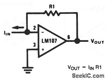
This basic circuit feeds the input current directly into the summing node (pin 2), causing the op-amp output to adjust and extract the same current from the summing node through resistor R1. The scale factor of the circuit is...
Power line fluctuations and cut-offs can damage electrical appliances connected to the line, particularly domestic appliances like refrigerators and air conditioners. When a refrigerator operates on low voltage, excessive current flows through the motor, leading to overheating and potential...
The current source in the diagram reacts very quickly to changes in the input signal and may be utilized in specific measurements. The differential amplifier IC1 ensures that the voltage across R2 is equal to the input voltage, represented...
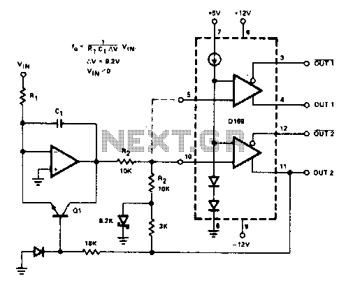
The D169 functions as a level detector, offering complementary outputs. An operational amplifier (op amp) is employed to integrate the input signal Vin, utilizing a time constant defined by the resistor R1 and capacitor C1. A negative input signal...
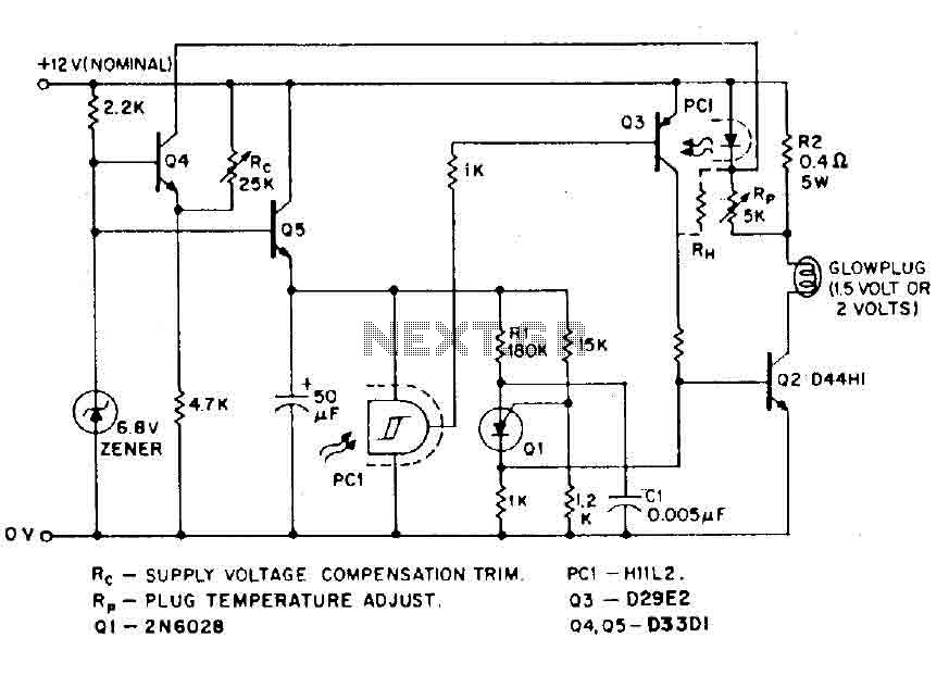
The circuit is designed for model airplanes, boats, and cars that utilize glow plugs for their miniature internal combustion engines (ranging from 0.1cc to 15cc). These engines are equipped with heavy batteries, high-tension coils, and capacitors necessary for classic...