
High Voltage power Supply
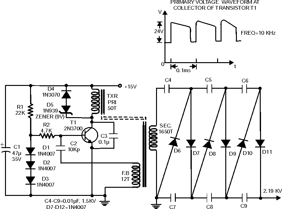
The high voltage power supply circuit operates effectively in a range of applications, particularly in biasing gas-discharge tubes and radiation detectors. The design is based on a transistorized blocking oscillator, which is critical for generating the high voltage output. The transformer, a central component in this circuit, is constructed using readily available ferrite cores. The assembly involves two E-shaped sections of the core, which are joined face-to-face after winding enamelled copper wire around a former.
In the circuit configuration, the primary and feedback windings are strategically arranged to establish sustained oscillations immediately upon powering the circuit. The oscillation waveform exhibits an asymmetrical duty cycle; however, this characteristic does not significantly impact the intended application. Should the circuit fail to initiate oscillations upon switching on, it may be necessary to reverse the connections of either the feedback or primary winding, but not both, to restore functionality.
The primary oscillation voltage is approximately 24V peak-to-peak (p-p), which is significantly amplified by the transformer’s high step-up ratio, resulting in an output voltage of around 800V p-p from the secondary winding. To further elevate this voltage to the desired level, a Cockcroft-Walton voltage multiplier is employed. This multiplier circuit incrementally boosts the voltage to produce a final output of approximately 2 kV in DC form.
It is important to note that the output voltage regulation is not optimal; however, with a constant load, adjustments can be made by varying the input supply voltage to achieve the desired output. The circuit is designed to operate with a 15V DC input to yield the 2 kV output. Caution is advised when increasing the input voltage, as exceeding component ratings may lead to electrical discharges or breakdowns, potentially damaging the circuit. A high voltage power supply is a very useful source which can be effectively used in many applications like biasing of gas-discharge tubes and radiation detectors etc. Such a power supply could also be used for protection of property by electric charging of fences. Here the current requirement is of the order of a few microamps. In such an application, high voltage would essentially exist between a live wire and ground. When this live wire is touched, the discharge occurs via body resistance and it gives a non-lethal but deterrent shock to an intruder.
The circuit is built around a single transistorised blocking oscillator. An important element in this circuit is the transformer. It can be fabricated on easily available ferrite cores. Two E sections of the core are joined face-to-face after the enamelled copper wire wound on former is placed in it. The details of the transformer windings are given in the Table. In this configuration, the primary winding and the feedback winding are arranged such that a sustaining oscillation is ensured once the supply is switched on. The waveform?s duty cycle is asymmetrical, but it is not very important in this application. Please note that if the oscillations do not occur at the ?switch-on? time, the transformer winding terminals of the feedback or the primary winding (but not both) should be reversed.
The primary oscillation amplitude is about 24V(p-p). This gets amplified with the large step-up ratio of the transformer and we get about 800V(p-p) across the secondary. A simple series voltage multiplier (known as Cockroft-Walton circuit) is used to boost up this voltage in steps to give a final DC of about 2 kV.
The output voltage, however, is not very well regulated. But if there is a constant load, the final voltage can be adjusted by varying the supply voltage. The present configuration gives 2 kV for an input DC voltage of 15 V. Though higher voltages could be achieved by increasing input supply, one word of caution is necessary: that the component ratings have to be kept in mind. If the ratings are exceeded then there will be electrical discharges and breakdowns, which will damage the device.
🔗 External reference
Related Circuits
DC Voltage Regulator (NPN & Zener Regulator) There are instances where it is handy to have a regulated DC voltage power supply for use on your model. A DC voltage regulator is an essential component in electronic circuits that provides...
Typically, an LED is powered by a DC supply; however, this circuit enables the LED to be powered by an AC supply. This circuit can serve as a power indicator for a water pump. The circuit for powering an LED...
This power monitoring device accurately measures voltage and current on a positive supply rail ranging from 7V to 80V through a straightforward I2C interface, as specified in the datasheet. It is particularly suitable for automotive applications that require power...
This is a high-brightness LED driver circuit. To provide a constant-voltage output, DC/DC regulators are typically used. However, a constant-current output is the preferred method for driving LEDs. The high-brightness LED driver circuit is designed to efficiently manage the power...
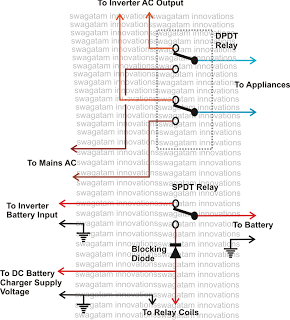
This inquiry has been presented multiple times on this blog regarding the implementation of a changeover selector switch for the automatic toggling of an inverter when AC mains power is available, and vice versa. The system must also enable...
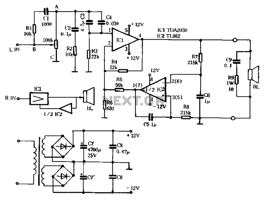
An amplifier circuit is depicted, utilizing two TDA2030 integrated circuits as power amplifiers. Additionally, a TT.082 is incorporated to form an active servo circuit for the TDA2030. The circuit features internal protections against overheating, overvoltage, and output short circuits,...