
HIGHWAY ALERT SIGNAL LAMP
The signal lamp for safe highway driving automatically emits a brilliant tricolor light when a vehicle approaches from the rear. It emits light for 30 seconds, turning off when the approaching vehicle overtakes. The ultra-bright blue, white, and red LEDs of the signal lamp provide high visibility to alert the approaching vehicle's driver, even during the day, enhancing safety at night or when stopping on the side of the highway. The circuit is designed to save considerable battery power and is built around two timer ICs, NE555 (IC1 & IC2). IC1 functions as a standard monostable multivibrator, while IC2 operates as an astable multivibrator. A Darlington phototransistor (L14F1, T1) serves as a photosensor to activate the monostable circuit. The collector of phototransistor T1 is connected to the trigger pin (pin 2) of IC1, which is kept high by resistor R1. When headlights from an approaching vehicle illuminate the phototransistor, it conducts and sends a short pulse to IC1, causing the output of IC1 to go high for a duration determined by resistor R2 and capacitor C1. The output of IC1 is fed to the base of transistor T2 via resistor R3. Transistor T2 conducts, driving transistor T3, which then sets the reset pin (pin 4) of IC2 to a high level. This action activates astable IC2, which alternates the switching on and off of the LED chain, creating an attractive tricolor flashing effect.
The circuit requires a 12V DC supply, which can be sourced from the vehicle's battery, ensuring proper polarity. The 555 timer IC is available in different packages, including an 8-pin metal can, an 8-pin mini DIP, or a 14-pin DIP. The 555 timer comprises 23 transistors, 2 diodes, and 16 resistors. Key pins include pin 6 (Threshold Terminal), which serves as the non-inverting input of comparator 1, and pin 7 (Discharge Terminal), which is internally connected to the collector of a transistor. A capacitor is typically connected between this terminal and ground.
The monostable multivibrator, often referred to as a one-shot multivibrator, generates a pulse whose duration is determined by the external RC network connected to the 555 timer. In a stable state, the output is approximately zero or at a logic-low level. When an external trigger pulse is applied, the output transitions to a high state (≈ VCC), remaining high for a duration determined by the external RC network before reverting to its logic-low state. The cycle repeats with each trigger pulse.
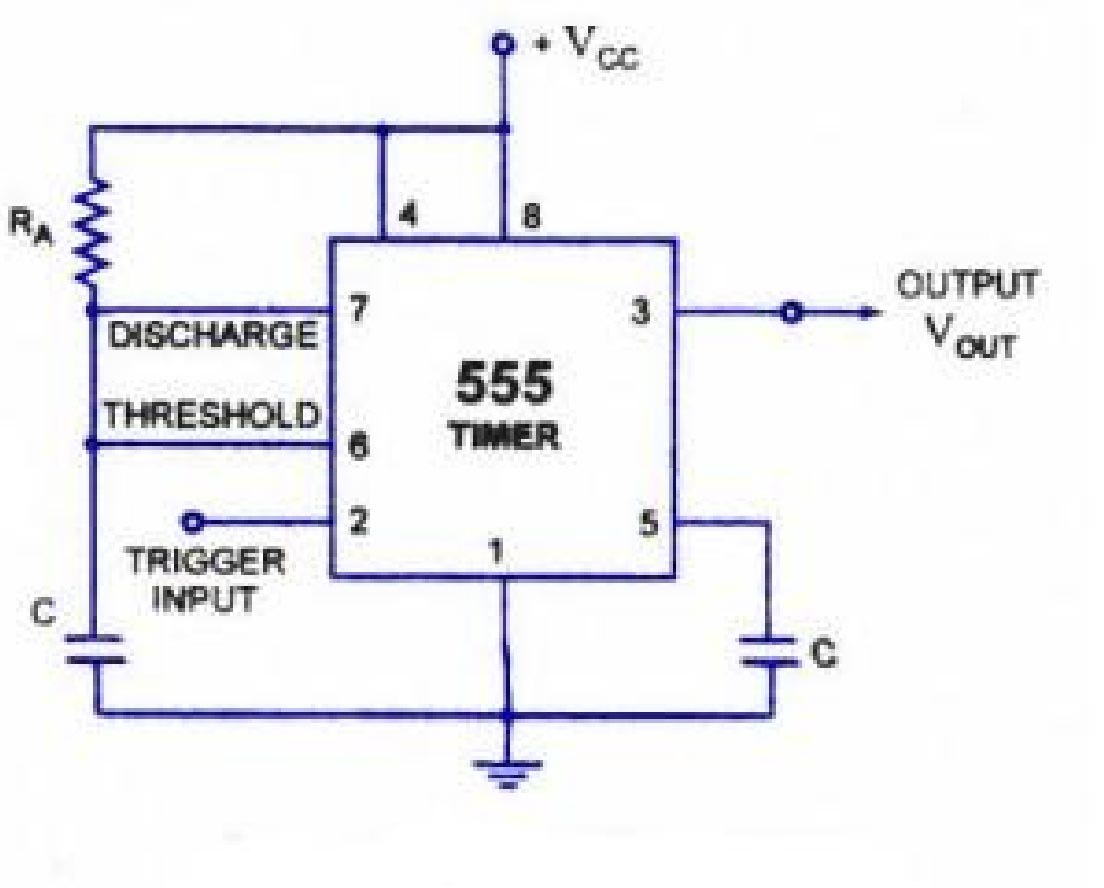
The astable multivibrator generates a square wave, with its period determined by the external components connected to the 555 timer. This configuration does not require an external trigger to change the output state, functioning as a free-running oscillator. The duration of the output being high or low is governed by two resistors and a capacitor connected externally to the timer.
Transistors, essential components in this circuit, amplify and switch electronic signals, featuring at least three terminals for connection to an external circuit. They enable control over the output power, which can exceed the input power, thus providing signal amplification. While some transistors are packaged individually, many are integrated within circuits.
Resistors, two-terminal components, produce a voltage across their terminals proportional to the electric current, in accordance with Ohm's law. Capacitors, passive components, consist of two conductors separated by a dielectric, storing energy when a voltage potential difference exists. Capacitors are widely utilized in electronic circuits to block direct current while allowing alternating current to pass, filter interference, and smooth power supply outputs.
Light-emitting diodes (LEDs) serve as semiconductor light sources, increasingly used for indicators and lighting applications. They emit light when forward biased, with the color determined by the semiconductor's energy gap. LEDs offer advantages over incandescent sources, including lower energy consumption, longer lifespans, improved robustness, and faster switching capabilities.
Phototransistors, designed to be light-sensitive, amplify variations in light. The Darlington phototransistor (L14F1) in this circuit serves as the photosensor, connected to the trigger pin of the monostable IC. The overall design of this signal lamp circuit enhances safety during highway driving by informing drivers of approaching vehicles and aiding in safe stops.The lighting system of a motor vehicle consists of lighting and signalling devices mounted or integrated to the front, sides, rear, and in some cases the top of the vehicle. The purpose of this system is to provideilluminationfor the driver to operate the vehicle safely after dark, to increase theconspicuityof the vehicle, and to display informati
on about the vehicle`s presence, position, size, direction of travel, and driver`s intentions regarding direction and speed of travel. Driving lamp" is a term deriving from the early days of night time driving, when it was relatively rare to encounter an opposing vehicle.
Only on those occasions when opposing drivers passed each other would the dipped or "passing" beam be used. The full beam was therefore known as thedriving beam. Turn signals are required to blink on and off, or "flash", at a steady rate of between 60 and 120 blinks per minute (Although some operate slower than this).
International regulations require that all turn signals activated at the same time (i. e. , all right signals or all left signals) flash in simultaneous phase with one another;North American regulations also require simultaneous operation, but permit side markers wired for side turn signal functionality to flash in opposite-phase. Worldwide regulations stipulate an audiovisualtelltalewhen the turn signals are activated; this usually takes the form of one combined or separate left and right green indicator lights on the vehicle`s instrument cluster, and a cyclical "tick-tock" noise generated electromechanically or electronically.
It is also required thataudioand/orvisualwarning be provided to the vehicle operator in the event of a turn signal`s failure to light. This warning is usually provided by a much faster- or slower-than-normal flash rate, visible on the dashboard indicator, and audible via the faster tick-tock sound.
Turn signals are in almost every case activated by means of a horizontal lever (or "stalk") protruding from the side of the steering column, though some vehicles have the lever mounted instead to the dashboard. The outboard end of the stalk is pushed clockwise to activate the right turn signals, or anticlockwise for the left turn signals.
This operation is intuitive; for any given steering manoeuvre, the stalk is pivoted in the same direction as theateering wheelmust be turned. This is the signal lamp for safe highway driving. The lamp automatically emits brilliant tricolour light when a vehicle approaches the rear side of your vehicle.
It emits light for 30 seconds that turns off when the approaching vehicle overtakes. The ultra-bright blue, white and red LEDs of the signal lamp emit very bright light to alert the approaching vehicle`s driver even during the day, giving additional safety during night or when you need to stop your vehicle on side of the highway. The circuit saves considerable battery power. The circuit is built around two timer ICs NE555(IC1& IC2). IC1 is designed as a standard monostable, while IC2 is designed as an astable. Darlington Phototransistor L14F1 (T1) is used as a photosensor to activate the monostable. The collector of Phototransistor T1 is connected to trigger pin 2 of IC1, which is normally kept high by resistor R1.
When headlight from an approaching vehicle illuminates the phototransistor, it conducts to give a short pulse to IC1, and the output of IC1 goes high for a 4 period determined by resistor R2 and capacitor C1. The output of IC1 is fed to the base of transistor T2 via resistor R3. Transistor T2 conducts to drive transistor T3 and its collector goes high to take reset pin 4 of IC2to high level.
This activates astable IC2, which switches on and off the LED chain alternately. The intermittent flashing of LEDs gives a beautiful tricolour flashing effect. 12 volt DC supply to the circuit, can be provided by your vehicle battery with proper polarity. The 555 IC is available as an 8-pin metal can, an 8-pin mini DIP(dual in package) or a 14-pin DIP. This IC consists of 23 transistors, 2 diodes and 16 resistors. Pin 6(Threshold Terminal):- This is the non-inverting input terminal of comparator1, which compares the voltage applied to this terminal with a reference voltage of +2/3 Vcc. Pin 7(Discharge Terminal):- This pin is connected internally to the collector of transistor and mostly a capacitor is connected between this terminal and ground.
Monostable multivibrator often called a one shotmultivibrator is a pulse generating circuit in which the duration of this pulse is determined by the RC network connected externally to the 555 timer. In a stable or standby state, the output of the circuit is approximately zero or a logic-low level. When external trigger pulse is applied output is forced to go high ( » VCC). The time for which output remains high is determined by the external RC network connected to the timer.
At the end of the timing interval, the output automatically reverts back to its logic-low stable state. The output stays low until trigger pulse is again applied. Then the cycle repeats. The monostable circuit has only one stable state (output low) hence the name monostable. The astable multivibrator generates a square wave, the period ofwhich is determined by the circuit external to IC 555.
The astable multivibrator does not require any external trigger to change the state of theoutput. Hence the name free running oscillator. The time during which the output is either high or low is determined by the two resistors and acapacitor which are externally connected to the 555 timer. The figure shows the 555 timer connected as an astable multivibrator. Initially when the output is high capacitor C starts charging towards VccthroughRAandRB. A transistor is a semiconductor device used to amplify and switch electronic signals. It is made of a solid piece of semiconductor material, with at least three terminals for connection to an external circuit.
A voltage or current applied to one pair of the transistor`s terminals changes the current flowing through another pair of terminals. Because the controlled (output) power can be much more than the controlling (input) power, the transistor provides amplification of a signal.
Some transistors are packaged individually but many more are found embedded in integrated circuits. The transistor is the fundamental building block of modern electronic devices, and its presence is ubiquitous in modern electronic systems. A resistor is a two-terminal electronic component that produces a voltage across its terminals that is proportional to the electric current through it in accordance with Ohm`s law A capacitor is a passive electronic component consisting of a pair of conductors separated by a dielectric.
When a voltage potential difference exists between the conductors, an electric field is present in the dielectric. This field stores energy and produces a mechanical force between the plates. An ideal capacitor is characterized by a single constant value, capacitance, which is measured in farads.
This is the ratio of the electric charge on each conductor to the potential difference between them. In practice the dielectric between the plates passes a small amount of leakage current. The conductors and leads introduce an equivalent series resistance and the dielectric has an electric field strength limit resulting in a breakdown voltage. They are widely used in electronic circuit to block the flow of direct current while allowing alternating current to pass, to filter out interferance, to smooth the output of power supplies, and for many other purposes.
They are used in radio frequency equipment to select particular frequencies from a signal with many frequencies. Alight-emitting diode(LED) is asemiconductorlight source. LEDs are used as indicator lamps in many devices, and are increasingly used forlighting. Introduced as a practical electronic component in 1962, early LEDs emitted low-intensity red light, but modern versions are available across thevisible, ultravioletandinfraredwavelengths, with very high brightness.
When a light-emittingdiodeis forward biased (switched on), electronsare able torecombinewithholeswithin the device, releasing energy in the form ofphotons. This effect is calledelectroluminescenceand thecolourof the light (corresponding to the energy of the photon) is determined by theenergy gapof the semiconductor.
An LED is often small in area (less than 1mm2), and integrated optical components may be used to shape its radiation pattern. LEDs present manyadvantagesover incandescent light sources includinglower energy consumption, longerlifetime, improved robustness, smaller size, faster switching, and greater durability and reliability When an external circuit is connected to the battery, then the battery drives electrons through the circuit and electrical work is done.
The battery has become a common power source for many household and industrial applications, and is now a multi-billion dollar industry. Phototransistor is Like diodes, all transistors are light-sensitive. Phototransistors are designed specifically to take advantage of this fact. The most-common variant is an NPN bipolar transistor with an exposed base region. Here, light striking the base replaces what would ordinarily be voltage applied to the base. So, a phototransistor amplifies variations in the light striking it. Note that phototransistors may or may not have a base lead (if they do, the base lead allows you to bias the phototransistor`s light response.
Here we use Darlington Phototransistor (L14F1) as a photosensor to activate the monostable IC1. The collector of phototransistor T1 is connected to trigger pin2 of IC1, which is normally kept high by resistor R1. When headlight from an approaching vehicle illuminates the phototransistor. It conduct to give a short pulse to IC1. In this project I have learned a lot about the SIGNAL LAMP scenario in the field of communication. This circuit is used for safe highway driving. This circuit inform the driver about the approaching vehicle. It also help the driver if the driver wants to stop for sometime on highway. It saves battery power. 🔗 External reference
Related Circuits
This signal generator is designed for the realignment of radio receivers. The unit is inexpensive and relatively simple but adequately serves its intended purpose. However, the output is not a pure sine wave, which may make it unsuitable for...
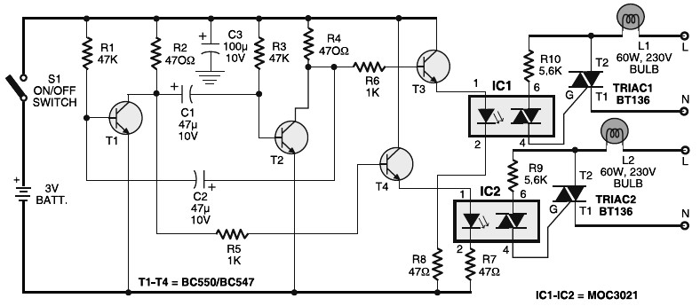
Portable 230V lamp flasher circuit diagram. The circuit is entirely transistorized and powered by a battery. A free-running oscillator circuit is implemented using two low-power, low-noise transistors, T1 and T2. One of these transistors remains in a conducting state...
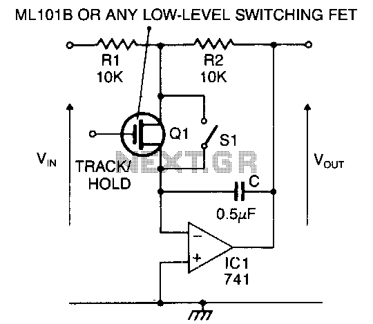
When the switch is closed or the FET is conducting, the circuit functions as an inverting amplifier with a gain of R2/Rl. The inverting terminal of the op-amp acts as a virtual ground, allowing the capacitor to remain charged...
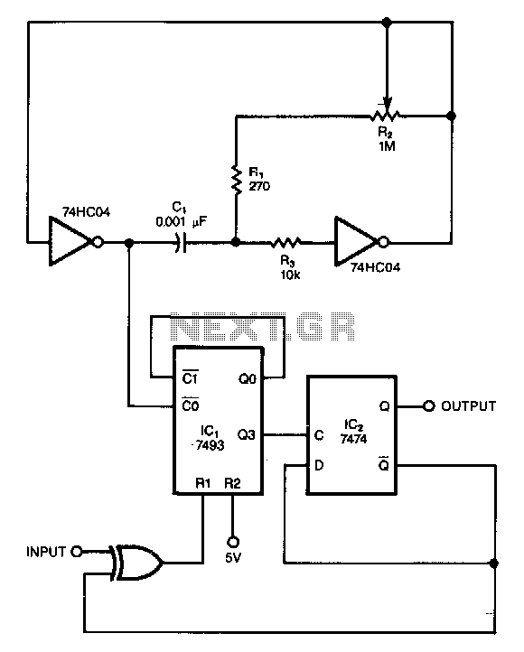
This circuit filters noise, such as glitches and contact bounce, from digital signals. It can be easily adjusted for a wide range of noise frequencies. The circuit's output changes state only if the input differs from the output long...
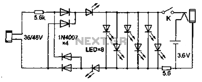
Also known as the Free lamp (commonly referred to as the Myanmar lamp by online sellers), this device operates using the voltage from a standard household fixed telephone line, eliminating the need for batteries or AC power. The lamp...
In the Fig.1, there exists a circuit, which is a sensitive switch that responds to AC signals of input, for signals above 5mV. It responds to all the signals from 50 Hz to 3 kHz, a region in which...