
Hijack Alarm
The described circuit functions as a vehicle anti-theft system that integrates multiple components to ensure the safety of the driver and the vehicle. The circuit is activated when the ignition is on and a door is opened, indicating a possible hijack scenario. Upon activation, a series of alerts are triggered, starting with a visual cue from an LED and an audio signal from a buzzer, which serves as an immediate warning to the driver. The timing components, specifically the capacitor C3, are critical in defining the alert duration, ensuring that the driver has sufficient time to respond.
The subsequent alarm phase is initiated after a predetermined delay, controlled by R7 and C4, which allows the thief time to distance themselves from the vehicle before the siren and buzzer sound continuously. This delay mechanism is crucial for enhancing the effectiveness of the alarm system, as it minimizes the risk of alerting the thief prematurely.
For added deterrence, the installation of a second siren within the vehicle is recommended. This not only amplifies the alarm's sound but also increases the likelihood of attracting attention in case of a theft attempt. The design allows for flexibility, permitting the omission of certain components if the user opts for a simpler system without the engine cut-out feature.
The reset mechanism is designed to be straightforward yet secure, requiring specific conditions to be met before the alarm can be reset. This ensures that the system remains active during a potential threat, giving the driver a chance to regain control of the situation. The use of a low-current reset button provides versatility in component selection, and the suggestion of a concealed reed switch adds an element of stealth to the system, further complicating any attempts by a thief to disable it.
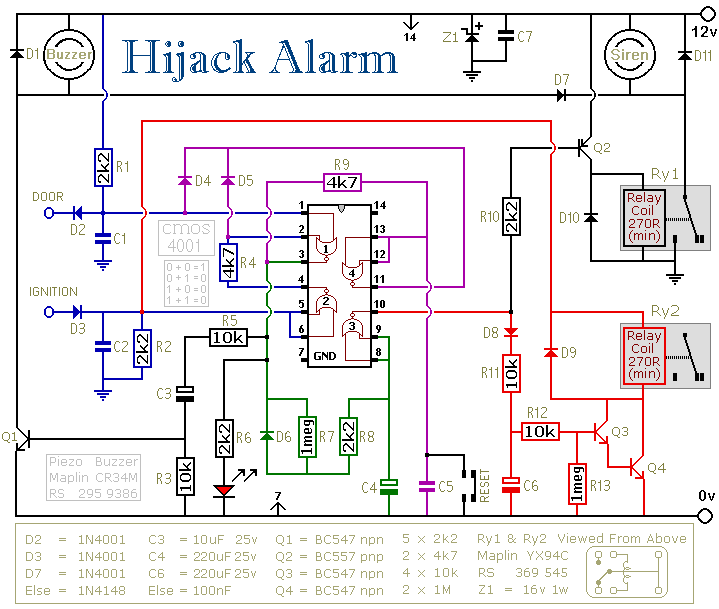
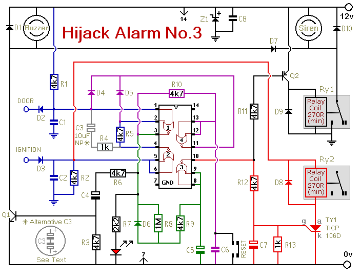
Overall, the design emphasizes safety, reliability, and user-friendliness, making it a robust solution for vehicle security.The first circuit was designed for the situation where a hijacker forces the driver from the vehicle. If a door is opened while the ignition is switched on - the circuit will trip. After a few minutes delay - when the thief is at a safe distance - the alarm will sound and the engine will fail.
Before fitting this or any other engine cut-out to you r vehicle - carefully consider both the safety implications of its possible failure - and the legal consequences of installing a device that could cause an accident. If you decide to proceed - you will need to use the highest standards of materials and workmanship. You`re going to trip this alarm unintentionally. When you do - the LED will light and the Buzzer will give a short beep. The length of the beep is determined by C3. Its purpose is to alert you to the need to push the reset button. When you push the button - the LED will switch-off. Its purpose is to reassure you that the alarm has in fact reset. If the reset button is not pressed then - about 3 minutes later - both the Siren and the Buzzer will sound continuously.
The length of the delay is set by R7 & C4. For extra effect - fit a second siren inside the vehicle. With enough noise going on - you may feel that it`s unnecessary to fit the engine cut-out. In which case - you can leave out D8, D9, R11, R12, R13, C6, Q3, Q4 & Ry2. Even if you missed the early warning provided by the Buzzer - there is still time to reset the alarm before Ry2 de-energizes - and the engine fails. This additional delay - currently about 1 minute - is set by C6 and R13. To reset the circuit you must - EITHER turn off the ignition - OR close all of the doors - before you press the reset button.
While BOTH the ignition is on - AND a door remains open - the circuit will NOT reset. The reset button carries virtually no current - so any small normally-open switch will do. Eric Vandel from Canada suggests using a reed-switch hidden behind (say) the dash - and operated by a magnet. I think this is an excellent idea. As Eric said in his email: - ". that should keep any thief guessing for a while. " Be the first of your friends to get free diy electronics projects, circuits diagrams, hacks, mods, gadgets & gizmo automatically each time we publish.
Your email address & privacy are safe with us ! 🔗 External reference
Related Circuits
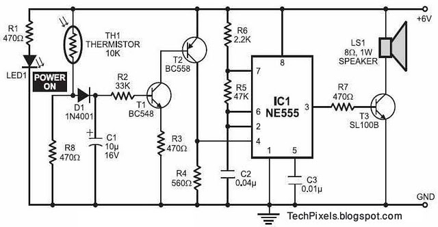
The following circuit illustrates a fire alarm circuit diagram utilizing the NE555 integrated circuit (IC). Features include functioning as a heat sensor and incorporating a 10 kilo-ohm resistor. The fire alarm circuit based on the NE555 IC is designed to...
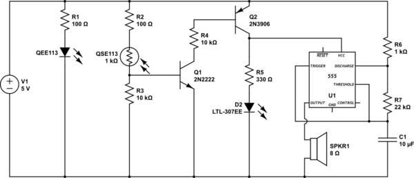
This circuit detects when a tube is empty and pulses a piezo buzzer at 5-second intervals. It is currently operational with a 5V supply on a breadboard but needs to be adapted for a 12V supply from a wall...
Beeper and/or LED remotely-operated via mains supply line. Pressing the pushbutton of the transmitter, a sound and/or light alert is activated in the receiver. The system uses no wiring or radio frequencies: the transmitted signal is conveyed into the...
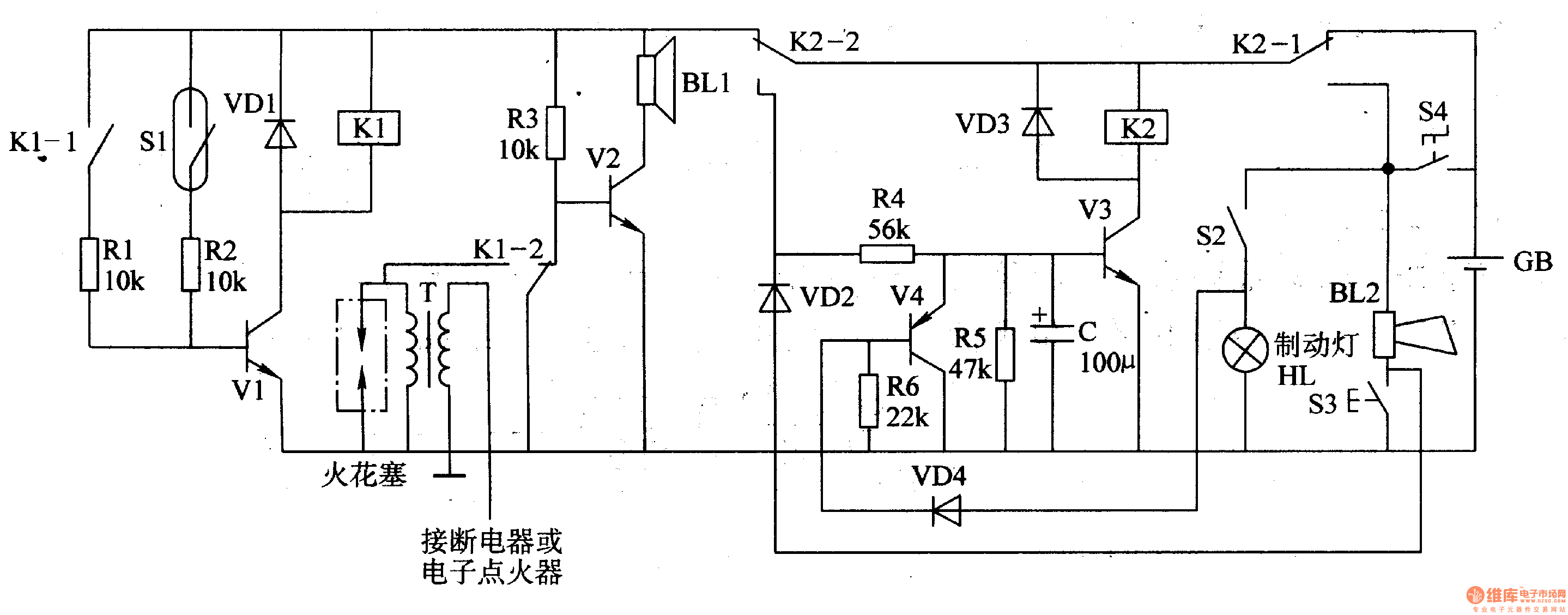
The circuit comprises a trigger circuit, an alarm control circuit, and a reset circuit for the alarm. The trigger circuit includes mercury switches (S1), a resistor, transistors (V1), and a relay (K1). The alarm control circuit is made up...
Similar to the initial two Hijack Alarms, this circuit is designed to activate if a door is opened while the ignition is switched on. After a delay of several minutes, allowing the thief to move a safe distance away,...
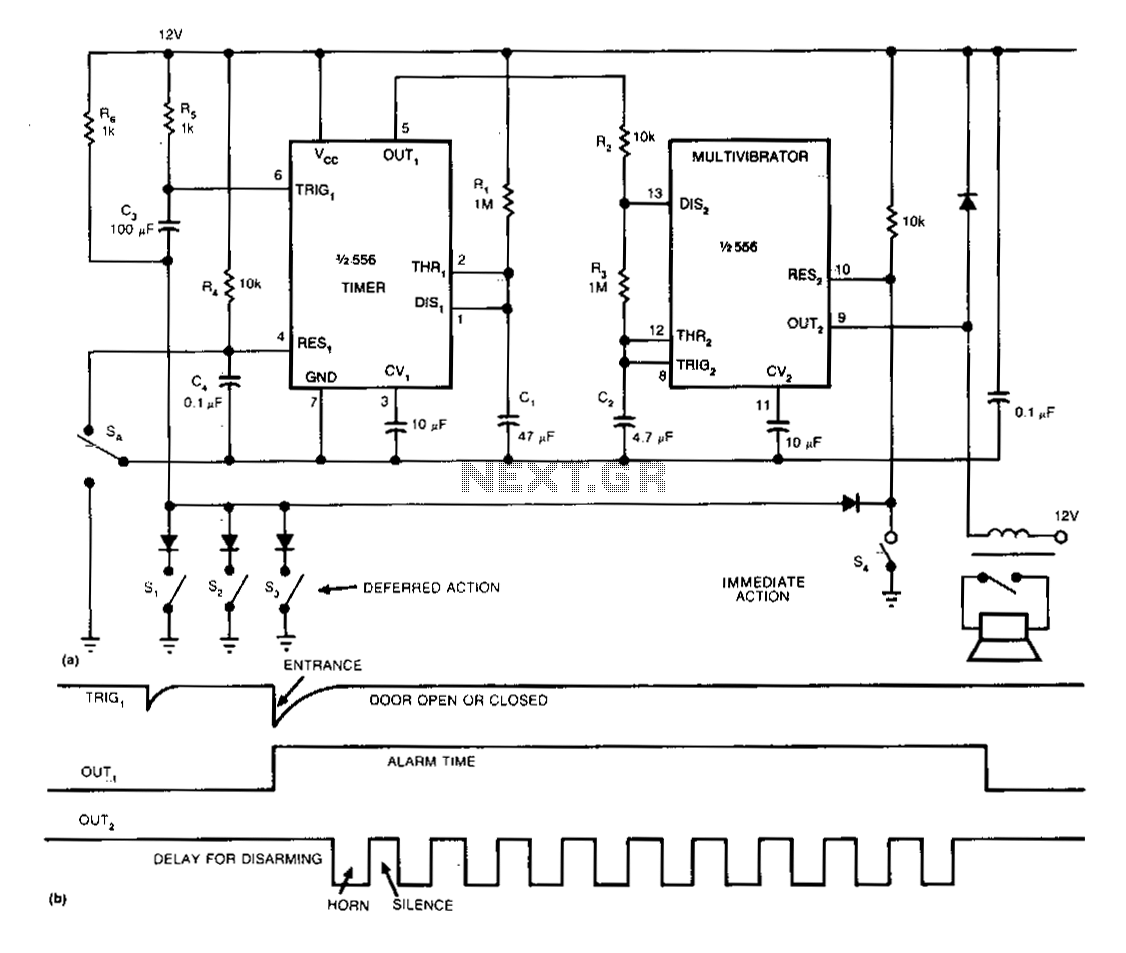
The single-chip burglar alarm circuit utilizes a dual 556 timer, drawing 10 mA of standby current, and produces a pulsing alarm signal that conserves battery energy. Once activated, the alarm remains operational, independent of the subsequent state of any...