
HOLTEK 9200B & 9170B DTMF Generator & Receiver

The circuit described involves a Keypad Interface that serves as an input mechanism for the Holtek 9200B DTMF Generator. The data lines from the keypad are essential for transmitting the pressed key information, which is encoded into DTMF tones by the generator. The connection to the data inputs (pins 6, 7, 8, and 9) allows the generator to interpret the keypad inputs directly.
The Chip Enable input (pin 1) is crucial for the operation of the DTMF generator. When this pin is held at a logic low state (0 volts), the generator becomes active and starts producing the corresponding DTMF tones. The output of the DTMF generator is then fed to the DTMF input of the Holtek 9170B DTMF Receiver, which is responsible for decoding the generated tones back into a digital format.
The receiver's functionality is indicated by the Data Valid output (pin 15), which transitions to a high state when a valid tone is detected. This output can be utilized to trigger further processing or actions within the system. Furthermore, the DTMF tones are decoded into a 4-bit binary number, available on output lines (pins 11, 12, 13, and 14), facilitating straightforward integration with digital logic circuits or microcontrollers for further processing or display.
In summary, this circuit effectively bridges the input from a keypad interface to DTMF tone generation and decoding, allowing for efficient communication and data processing within electronic systems that utilize DTMF signaling.The 4 data lines from the Keypad Interface go straight into the data inputs of the Holtek 9200B DTMF Generator (pins 6, 7, 8 & 9), and the Inverted Chip Enable output on the Keypad Interface goes into the Chip Enable Input on the Holtek 9200B DTMF Generator (pin1). When the Chip Enable line is at logic 0, a DTMF tone is generated from the DTMF out put (pin 13) with respect to ground. This is an `Active Low` input so logic 0 will enable the chip. The DTMF output is then taken to the DTMF input line of the Holtek 9170B DTMF Receiver. When a tone is present, the Data Valid output goes high (pin 15). Also the DTMF tone will be decoded to a 4 bit binary number on the output lines (pins 11, 12, 13 and 14). 🔗 External reference
Related Circuits
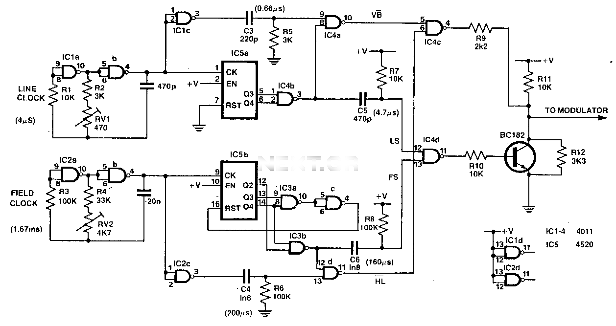
This circuit serves as a simple, low-cost crosshatch generator for convergence and geometry adjustments in color televisions. It is driven by two clock signals, one for horizontal drive (IC1ab) and another for vertical drive (IC2ab). The outputs from these...
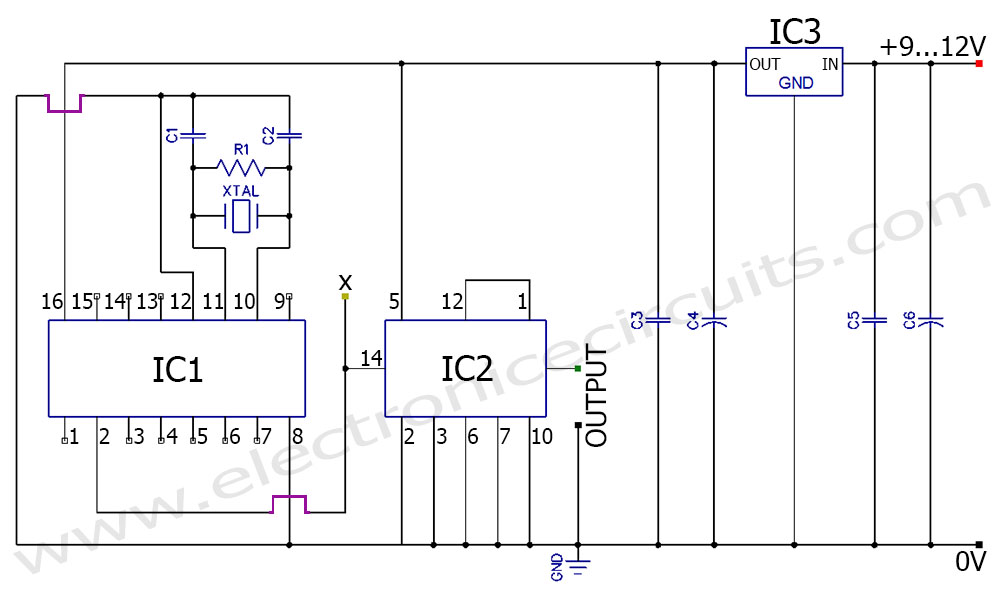
A frequency generator circuit capable of producing 50 Hz and 60 Hz outputs using a crystal oscillator. This oscillator can be utilized to generate precise frequency signals. This frequency generator circuit employs a crystal oscillator as its core component, which...
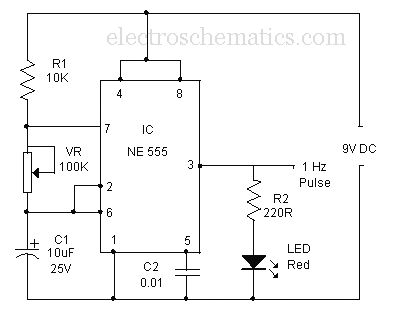
A simple buzzer is being converted into an oscillating buzzer to produce a sound similar to that of an automobile's reverse indicator. The schematic provided is borrowed from electroschematics.com. The intention is to replace the LED in the circuit...
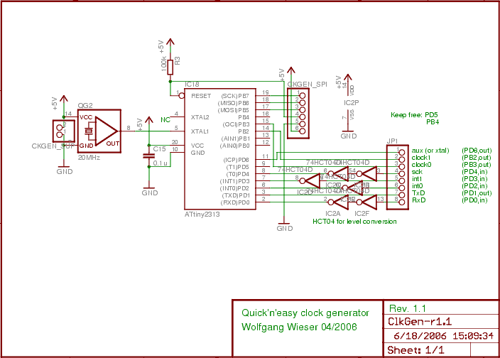
The design generates varying sampling clock write strobe pulses using an ATtiny2313 microcontroller from Atmel. For a 10MHz sampling clock, a 20MHz clock is required for the ATtiny2313, necessitating a power supply of 5V instead of 3.3V, which is...
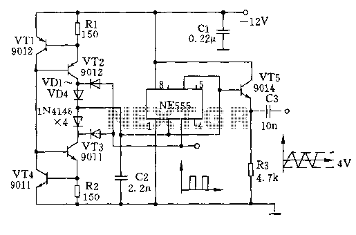
The circuit depicted involves transistors VT1, VT2, and resistor R1, which form a constant current source for charging capacitor C2 in a linear manner. Transistors VT3, VT4, and resistor R2 create a constant current source for discharging capacitor C2,...
Superheterodyne receivers have been mass-produced since around 1924, but for reasons of cost did not become successful until the 1930s. Before World War II, other, simpler receiver technologies such as the TRF receiver and the regenerative receiver were still...