
home automation Installation

The light controls mentioned are typically mounted in place of wall switches. An example is the 2466SW wall-mounted relay control compatible with fluorescent lights. There are alternative options for this component, including dimmable controls for incandescent lights, such as the 2466DW model. It is crucial to only purchase dimmable controls for traditional incandescent bulbs; for all other applications, relay controls are recommended. The system also includes two access points/wireless phase couplers (model 2443PR), which serve multiple functions: they accept signals from Insteon wireless remote controls (model 2440BK) and bridge the two sides of a typical house wiring system, providing a solution to issues previously encountered with X-10 systems.
A system controller (model ISY-26) enables home automation, allowing programming for activities that simulate occupancy while away and the ability to integrate older X-10 wireless or wired controls, such as motion sensors and remote controls, with the Insteon system. The Insteon controls listed are compatible with existing X-10 systems, as they are designed to work with both protocols. Therefore, purchasing some of these controls can serve as an initial step toward upgrading to an Insteon system. The components listed represent more than just a minimal Insteon system. A basic setup would consist of a few light switch controls, two wireless phase couplers, and a remote control. The smallest functional Insteon system would include two or three light switch controls, allowing for the control of an entire room's lighting from any one switch. This can be achieved without a system controller or remote control, underscoring that while a system controller is a beneficial addition, it is not a requirement.
It is essential to reiterate that unless one possesses the necessary skills and familiarity with home electrical systems and their associated risks, it is advisable to hire a qualified electrician for such tasks. This section will outline the simplest installation procedure: wiring an Insteon switch. Mastery of this procedure is critical due to its frequent application. It is important to note that improper connections, particularly with three-wire Insteon (and X-10) controls, can lead to device failure, especially if the neutral (white) connection is not securely made.
To begin, remove the old switch, ensuring that no multiple connections unravel during the process. It may be prudent to temporarily replace the wire nuts to maintain organization. Locate the Insteon control's clear plastic "set" button and pull it out to disable the control, providing additional security against damage. Connect the "Neutral" (white) wire of the Insteon control to the bundle of white wires using an appropriately sized wire nut; it is advisable to use a new wire nut if the original is not adequately sized. This connection must be secure to prevent damage to the control. Care should be taken to avoid confusion, as U.S. domestic wiring typically employs black for line wires and may also use black for load wires. Maintaining the original wire groupings is crucial to prevent mistakes that could damage the Insteon control.
Before replacing the switch plate, document the Insteon control's address, which is located at the front lower left of the device. The address consists of six characters grouped in pairs and separated by periods. This step is particularly important for larger installations to avoid confusion. Repeat the installation procedure for each Insteon control, remaining cautious of transitioning between powered and unpowered locations. Many homes have light switches that operate in tandem, such as those at either end of a hallway or staircase. Older X-10 systems utilized satellite switches for this purpose, but Insteon controls utilize a more efficient method. They employ computer logic to connect multiple controls rather than relying on physical wiring, simplifying the installation process and allowing for the addition of more controls without requiring different types of switches.
In scenarios where two switches control the same load, one Insteon control can be wired in the box containing the load wire, while a second control is installed in the other box, connecting the "Line" (black) and "Neutral" (white) wires, but leaving the load connection disconnected (cover the red "Load" wire with a wire nut to prevent short circuits). This may seem unconventional, but Insteon controls are designed to function together even if only one is connected to the load; both controls must be powered.
The final hardware installation consideration involves the placement of two wireless access points (model 2443PR), which facilitate communication between the two legs of the house's electrical system and enable access for Insteon remote controls. To install the second access point, plug it into a different location. If the LED indicator is flashing or dim, try different outlets until a bright and steady LED is achieved, indicating successful detection of an outlet on a separate electrical leg. Once the second access point is positioned, press its "set" button, which should result in both access points displaying dim and steady LEDs, confirming successful configuration.First and foremost, if you are not handy with tools and electrical systems, please. hire an electrician instead of trying to undertake this task yourself. And have the electrician read this page for specific cautions and advice. I offer this advice because a house electrical system can kill the unwary. You`ve been warned. Okay, warning g iven. From this point onward, I will make the assumption that my readers are (1) homeowners skilled with electrical systems, (2) professional electricians, or (3) curious people who just want to read the article but who aren`t planning to self-administer shock therapy. My Insteon system is limited in scope ” I have only relay controls (primarily 2466SW units) and no dimmers because my system is almost entirely compact fluorescents.
This means these instructions won`t cover all possibilities ” a typical installer will need to include some things I don`t use. But this article will educate you in the basics and get you started. Also, in a later section, I describe in detail what I regard as the heart of a sophisticated Insteon system ” a system controller with enough brain power to make the entire system modestly intelligent.
Some light controls, normally mounted in place of wall switches. An example would be the one I have dozens of ” the 2466SW wall-mounted relay control that works with fluorescent lights. There are many other options for this element, including dimmable controls for those who have incandescent lights and want to be able to control the light level in a room (example: 2466DW ).
A caution ” only buy dimmable controls for ordinary, old-fashioned incandescent light bulbs. For all other purposes, get a relay control. Two access points / wireless phase couplers ( 2443PR ) that serve multiple purposes ” they accept signals from Insteon wireless remote controls ( 2440BK ), and they bridge the two sides of a typical house wiring system, a new solution to the problem discussed earlier with respect to X-10 systems. A system controller ( ISY-26 ). This device allows you to automate your house, make it look lived in while you are away, schedule activities, and it also allows you to accept and translate any older X-10 wireless or wired controls such as motion sensors and remote controls, and use those controls with the Insteon system.
The Insteon controls listed above will work just fine with a pre-existing X-10 system, because Insteon controls are essentially bilingual. So one can buy some of these controls for use in an X-10 system as the first step in an Insteon upgrade plan.
The list above contains much more than a minimal Insteon system. A minimal system would be a handful of light switch controls, the two wireless phase couplers, and a remote control. The very smallest meaningful Insteon system would be two or three light switch controls, installed in a way that allows you to control an entire room of lights by turning on any one of them.
This can be accomplished without a system controller or a remote control. I want to emphasize these points to avoid creating the impression that you must have a modem and a system controller to use an Insteon system ” you don`t. I think a system controller is a very nice addition, but it`s not a requirement. WARNING: Again, unless you are handy with tools and are familiar with home electrical systems and their risks, don`t undertake this kind of work ” hire an electrician.
This section will show the simplest installation activity, that of wiring an Insteon switch into place. You will be performing many repetitions of this activity, and for a number of reasons it is essential to learn how to do it properly.
Some readers may wonder why I go into such detail about this ” after all, isn`t it true that if you get it wrong, if you don`t connect it just so, or if you don`t tighten the wire nuts snugly, the switch simply won`t work, and you can try again Well, no, as it happens, with three-wire Insteon (and X-10) controls, it`s a bit more complicated than that ” you can very easily destroy the control, in particular if the neutral (white) connection is not made securely and correctly. Remove the old switch, being careful not to allow any multiple connections to become unraveled as you remove the wire nuts.
You may want to put the wire nuts back in place temporarily to assure that the original wire bundles don`t become disorganized. Locate and pull the Insteon control`s clear plastic "set" button out, so it protrudes from the switch.
This disables the control and offers additional security against damage. Connect the "Neutral" (white) Insteon control wire to the bundle of white wires using a suitably-sized wire nut. Don`t necessarily use the original wire nut ” it may never have been adequately sized, and the new wire sizes may not fit properly into the original nut.
And remember ” if this specific connection is not made securely, the control may be destroyed. Pay very careful attention to this connection. Obviously there is some possibility for confusion here, because in typical U. S. domestic wiring practice, the line wires are black and the load wire may also be black. So be very careful to keep the wires grouped as they were originally ” this is another area where a mistake could easily destroy the Insteon control. Before replacing the switch plate, make a note of the Insteon control`s address, which is printed at the front lower left of the control.
The address will consist of six characters, grouped in pairs, separated by periods. Take this step for each Insteon control you install, and include the control`s location. This step is especially important for large installations, where the possibility for confusion is greater. Repeat the above procedure for as may Insteon controls as you intend to install, but remember that you may move from an electrically disabled location to an enabled location without realizing it.
Not all of us have the luxury of shutting the entire house down ” remember to test before touching. Nearly all houses have light switches that are expected to operate in tandem, such as at each end of a long hallway, or on a staircase, where each end of the passage has an independent light switch. The older X-10 controls had a special satellite switch for this case, but Insteon controls handle this in a different (better) way ” they have just one kind of control, and the connection between two ends of a passage or staircase is made using computer logic rather than wires.
The advantages should be obvious ” you only have to buy one kind of control for all locations, and better, if you want more than two controls to operate together (such as a large room with three or more light switches), this is easily accomplished. If you have a location where two separate switches operate in tandem on the same load, simply wire one of two Insteon controls into whichever electrical box contains the load wire as shown above, then install a second Insteon controller in the other box, connecting the "Line" (black) and "Neutral" (white) leads, but with no load connection (put a wire nut over the red "Load" wire to prevent an inadvertent short-circuit).
Yes, I know this sounds crazy at first glance ” how can the second switch do its job without being connected to the load Well, Insteon controls are pretty clever ” you can make one control act in concert with another, even if only one of them is actually connected to the intended load. The only requirement is that both controls need to be powered ” they should both have their "Line" (black) and "Neutral" (white) wires connected.
Only one of them needs to have a "Load" connection. This page deals with hardware installation issues, and the placement of two wireless access points is one of the last physical installation issues (most of the remaining activities involve configuration and software activities). As explained above, the wireless access points ( 2443PR ) serve two purposes ” they open a communication pathway between the two house wiring legs, and they grant Insteon remote controls access to the house system.
Go to another location for the second access point and plug it in. If its LED is flashing or dim, move to a different outlet until you find one where the LED burns bright and steady (the point of this step is to allow the access points to automatically detect outlets that are on separate legs of the house`s electrical system). Return to the location of the first access point and press its "set" button. This should make the LEDs on both access points glow dim and steady, indicating a successful configuration.
🔗 External reference
Related Circuits
.png)
Have you ever considered implementing your own home security alarm system? It is one of the simplest and most interesting circuits for electronics beginners. The new home security equipment utilizes a Light Dependent Resistor (LDR) to detect security breaches....
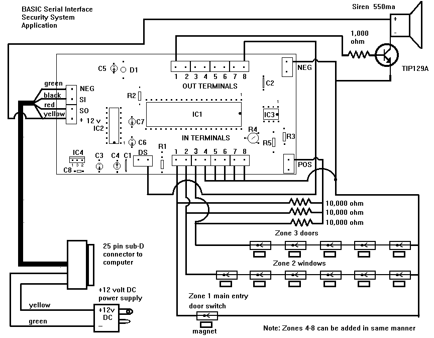
The security system application and program offers a simple demonstration of the BASIC Serial Interface. By adding only a few door and window switches, a transistor, a siren, and a few lines of BASIC program the interface can become...
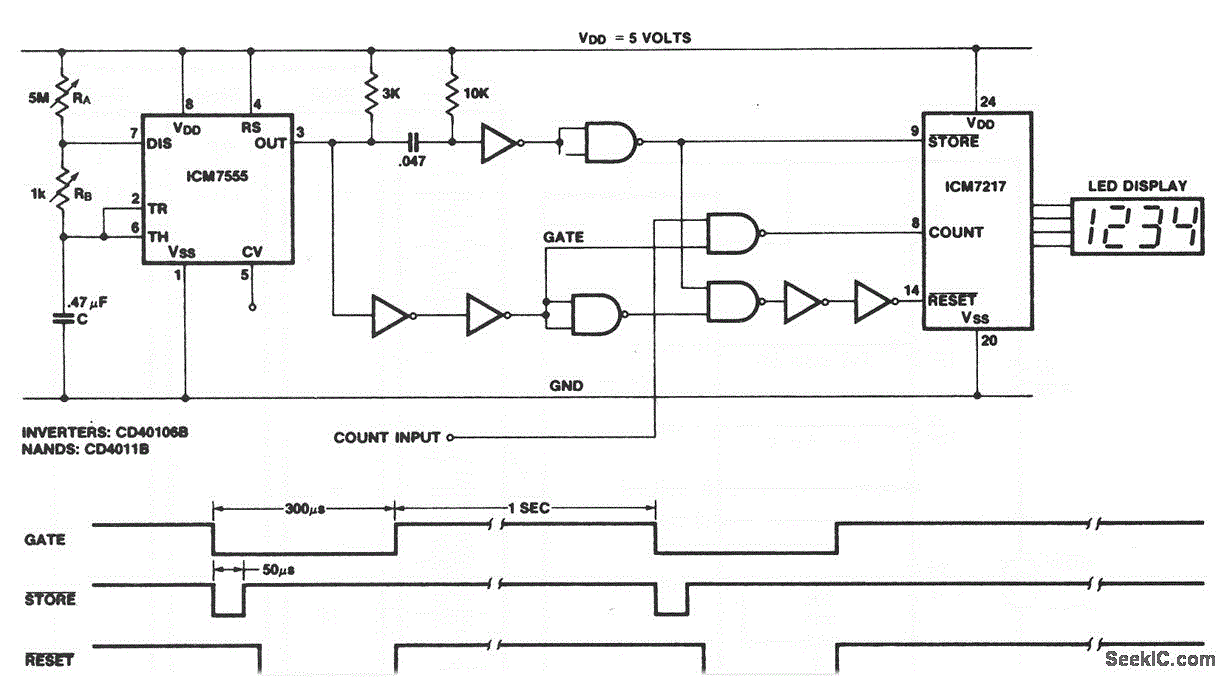
This circuit illustrates the configuration of an ICM7217 and an ICM7555 designed as a basic frequency counter. The connections between the ICM7217 and a common-cathode LED display are depicted in Figure 12-18. Calibration of the frequency counter is accomplished...
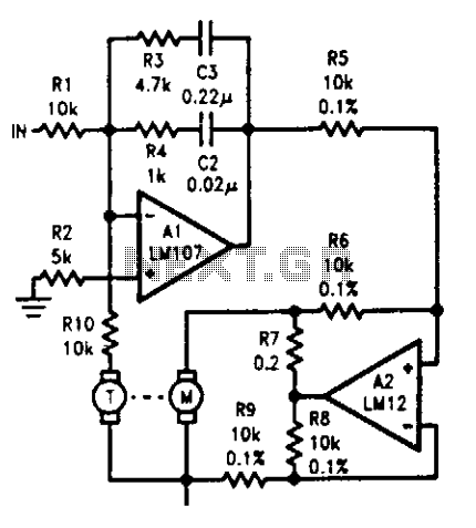
The tachometer, mounted on the same shaft as the DC motor, functions as a generator, producing a DC output voltage that is proportional to the motor's speed. A summing amplifier, labeled as Al, manages its output to ensure that...

When powering a computer on and off, various peripherals, including printers, screens, scanners, and others, often need to be activated or deactivated simultaneously. By implementing a system that manages these peripherals... In modern computing environments, managing the power states of...
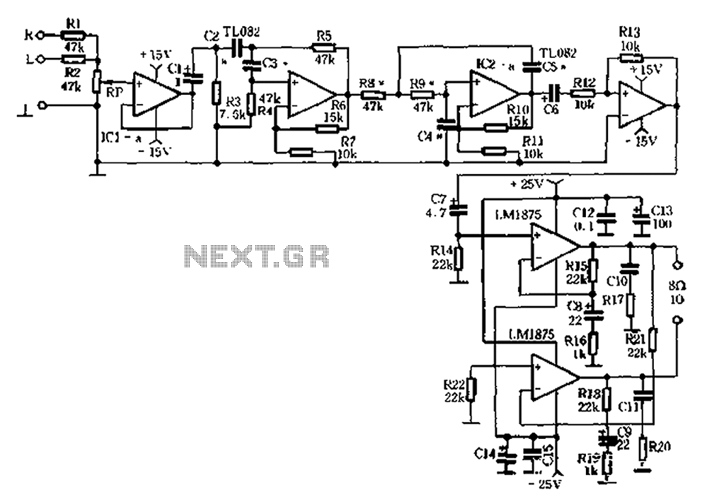
Audio equipment utilizes the left and right channel signal from the former speaker output terminals. The Rl and RZ mixed units are processed through a buffer (IC1a) before passing through a high and low pass filter. The filter employs...